
Device and method for fixing shaft tube and plate spring seat before welding

A leaf spring seat, front fixing technology, applied in auxiliary devices, welding equipment, auxiliary welding equipment, etc., can solve problems such as affecting the service life of parts and vehicles, affecting the appearance quality of the painted surface, and unstable product qualification rate. , to achieve stable qualification rate, avoid welding slag from entering the braking system, and eliminate the need for spot welding positioning operation.

Pending Publication Date: 2022-01-21
江苏宝京汽车部件有限公司
View PDF5 Cites 0 Cited by
  • Summary
  • Abstract
  • Description
  • Claims
  • Application Information

AI Technical Summary

Problems solved by technology

However, there are at least the following defects in this welding method: 1) due to the need for scribing and positioning, and the axle has been assembled and painted on the axle at this time, re-scribing will inevitably affect the appearance quality of the painted surface; 2) because the axle After the assembly is completed, spot welding is performed on the surface to locate the relative position of the axle and the leaf spring seat. During the spot welding process, spatter such as welding slag can easily enter the interior of the brake system, causing damage to the car body parts, thereby affecting the parts. The service life and the service life of the car; 3) In addition, the welding method is positioned by manual measurement, not only will there be errors, but the entire production process will take a long time, the production efficiency is not high, the product qualification rate is unstable, and the production cost is high.

Method used


Image

  • Device and method for fixing shaft tube and plate spring seat before welding
  • Device and method for fixing shaft tube and plate spring seat before welding
  • Device and method for fixing shaft tube and plate spring seat before welding

Examples


Embodiment Construction

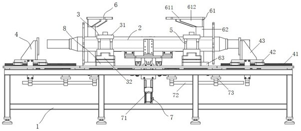
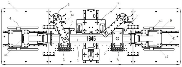
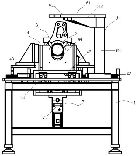
[0031] The technical scheme of the present invention will be clearly and completely described below in conjunction with the embodiments and the accompanying drawings. Obviously, the described embodiments are only preferred embodiments of the present invention, not all embodiments, nor are they intended to be a reference to the present invention. For other forms of limitations, any skilled person who is familiar with this field may use the disclosed technical content to make changes or remodel equivalent changes. However, any simple modifications, equivalent changes and modifications made to the above embodiments according to the technical essence of the present invention without departing from the content of the technical solution of the present invention still belong to the protection scope of the technical solution of the present invention.

[0032] This embodiment is a fixing device before welding of a shaft tube leaf spring seat and its use method. The fixing device before ...


PUM


Abstract

The invention discloses a device and a method for fixing a shaft tube and a plate spring seat before welding. The fixing device comprises a fixing base and a fixing assembly arranged on the fixing base and used for fixing the shaft tube and the plate spring seat. The fixing assembly comprises a centering mechanism, a manual placing pin and a pressing mechanism. The centering mechanism is used for positioning the corresponding position relation of the shaft tube and the plate spring seat in the axial direction and the radial direction; the plate spring seat comprises an upper plate spring seat and a lower plate spring seat; the manual placing pin is used for limiting the position relation between the upper plate spring seat and the lower plate spring seat; and the pressing mechanism is used for pressing and attaching the upper plate spring seat and the lower plate spring seat to the shaft tube and then welding. Therefore, the scribing time and the spot welding fixing time are saved, and the production efficiency is improved; positioning is carried out according to the position relation of corresponding parts, so that the positioning precision is high; and meanwhile, damage caused by welding operation on the assembled product is avoided, the working efficiency is improved, the product quality consistency is good, and the percent of pass is stable.

Description

technical field [0001] The invention relates to a fixing device and method for a shaft tube leaf spring seat before welding. Background technique [0002] The leaf spring is one of the traditional elastic elements in the suspension system of automobiles and trucks. It can undertake the transmission of force and moment in all directions, and determine the trajectory of the wheel movement, and play a guiding role; it can also generate a certain The resistance of the car body promotes the vibration attenuation of the body and plays a role in shock absorption. [0003] After the axle of the integrated semi-trailer is assembled, the leaf spring seat needs to be welded according to the process and drawing requirements. The traditional welding method of the axle leaf spring seat is to first determine the position by measuring and marking, and then weld. However, there are at least the following defects in this welding method: 1) due to the need for scribing and positioning, and th...

Claims


Application Information

Patent Timeline
Patent Type & Authority Applications(China)
IPC IPC(8): B23K37/00B23K37/04B23K37/047
CPCB23K37/00B23K37/0443B23K37/047
Inventor 赵木森冯炜
Owner 江苏宝京汽车部件有限公司
Learn More