
Rotary sawing machine for pipes

A technology for sawing machines and pipes, applied to metal sawing equipment, sawing machine devices, metal processing equipment, etc., can solve the problems of pipe surface damage, high noise, and increased transportation costs, and achieve reduced wear and faster sawing speed Effect

Pending Publication Date: 2022-01-21
金凯达(佛山)智能装备有限公司
View PDF0 Cites 3 Cited by
  • Summary
  • Abstract
  • Description
  • Claims
  • Application Information

AI Technical Summary

Problems solved by technology

And the loading frame of this structure has the following disadvantages: 1. The current feeding method pipe will drop from the jacking block to the blocking block, and then fall to the support roller group, which will cause two impacts , this will cause damage to the surface of the pipe, and the noise will be louder; 2. The current loading rack is welded by profiles, so a support frame can only support pipes of one specification group, when the length of the pipe When the gap is large, different lengths of loading racks are required to support; in addition, when the pipe is long, the length of the loading rack is also very long, resulting in increased transportation costs

Method used


Image

  • Rotary sawing machine for pipes
  • Rotary sawing machine for pipes
  • Rotary sawing machine for pipes

Examples


Embodiment Construction

[0024] The present invention will be described in further detail below through specific examples.

[0025] The longitudinal and axial directions mentioned in this embodiment are along the length of the pipe, and the transverse direction is the direction perpendicular to the longitudinal direction.

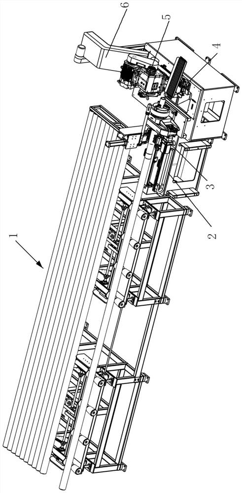
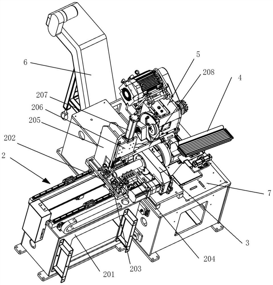
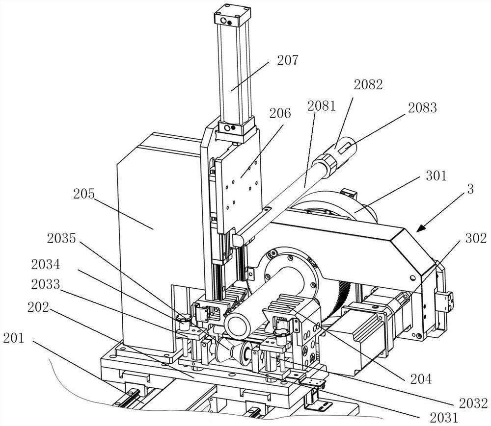
[0026] Such as Figure 1 to Figure 7 As shown, a pipe rotary sawing machine includes an automatic feeding rack 1 for placing pipes, the automatic feeding rack 1 includes a material rack, and an inclined discharge platform 104 is arranged above the material rack. The lower side of the discharge platform 104 on the material rack is provided with a blocking material guide plate 105, the upper end surface of the blocking material guide plate 105 is set as an inclined material guide slope 1052, and the blocking material guide plate 105 is close to the material discharge platform 104. The upstream side is provided with an upstream material guide inclined surface 1051, and a support roll...


PUM


Abstract

The invention discloses a rotary sawing machine for pipes. The rotary sawing machine for the pipes comprises an automatic feeding frame, an automatic feeding device and a sawing device, wherein the sawing device comprises a machine base; a rotary clamp assembly is installed on the machine base; the automatic feeding device is used for longitudinally feeding pipes into the rotary clamp assembly; a sawing head driven by a feeding power device is installed on the machine base in a sliding or swinging mode; a material receiving device for receiving sawed materials is further arranged on the machine base; and the material receiving device is matched with the rotary clamp assembly. According to the sawing machine, the rotary clamp assembly is used for clamping a pipe to rotate around the center of the pipe, then the sliding or swinging sawing head is used for sawing the pipe, so that the pipe can be completely cut off only by cutting the thickness of the pipe wall of the pipe through a saw blade of the sawing head, so that loss of the saw blade is reduced.

Description

technical field [0001] The invention relates to a pipe rotary sawing machine, which is used for rotary sawing of pipes. Background technique [0002] At present, the saw blade is mainly used in the pipe sawing machine to saw and the pipe is clamped and fixed, and then the rotating saw blade is used to gradually feed to cut the pipe. Therefore, the current pipe sawing machine mainly includes a feeding rack. , used to place the pipe and feed the pipe to the pinch mechanism, the sliding or yaw sawing head driven by the feed power device, the pipe is fed into the clamp assembly by the pinch mechanism, the clamp assembly is generally It includes an upstream clamp and a downstream clamp. The upstream clamp and the downstream clamp cooperate with each other to clamp the pipe. The sawing head approaches the pipe to achieve sawing by sliding or swinging. The cutting position of the saw blade is located between the upstream clamp and the downstream clamp. Between the clamps, the enti...

Claims


Application Information

Patent Timeline
Patent Type & Authority Applications(China)
IPC IPC(8): B23D45/12B23D47/00B23D47/04
CPCB23D45/12B23D47/04B23D47/042B23D47/045B23D47/00
Inventor 柯晓华
Owner 金凯达(佛山)智能装备有限公司
Learn More