A Shaft Current Protection Structure of Variable Frequency Motor

A protective structure and variable frequency motor technology, which is applied in the direction of structural connection, electromechanical devices, electrical components, etc., can solve the problems of increasing the internal installation space and cost of the motor, and the inconvenience of rectification of the existing motor, etc., to achieve platformization and convenient installation and maintenance Effect

Active Publication Date: 2022-06-17
ZHEJIANG ZHONGCHE SHANGCHI ELECTRIC CO LTD
View PDF7 Cites 0 Cited by
  • Summary
  • Abstract
  • Description
  • Claims
  • Application Information

AI Technical Summary

Problems solved by technology

[0003] In the field of new energy vehicle motor applications, due to factors such as product structure and cost, insulating end caps and insulating bearings are rarely used. The use of grounding carbon brushes or conductive rings requires additional consideration of the installation space of the motor, and it is very difficult for the motor that has already been installed. Difficult to rectify
[0004] At present, in the field of new energy vehicle motors, the shaft current problem is mostly treated with a conductive ring. The conductive ring conducts electricity through the conductive fiber fixed in the ring and the shaft. Compared with the ground carbon brush, the conductive fiber has good conductivity and wear resistance. , maintenance-free and other advantages, due to the large conductive ring, it will need to increase the installation space and cost inside the motor, and it is very inconvenient for the rectification of the existing motor

Method used


Image

  • A Shaft Current Protection Structure of Variable Frequency Motor
  • A Shaft Current Protection Structure of Variable Frequency Motor
  • A Shaft Current Protection Structure of Variable Frequency Motor

Examples


Embodiment Construction

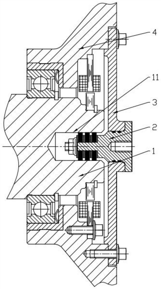
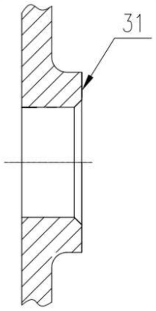
[0040] refer to Figure 1 to Figure 20 The embodiments of the present invention will be further described.

[0041] In the description of the present invention, it should be noted that for orientation words, such as the terms "center", "horizontal (X)", "longitudinal (Y)", "vertical (Z)", "length", " Width, Thickness, Top, Bottom, Front, Back, Left, Right, Vertical, Horizontal, Top, Bottom, Inside ", "outside", "clockwise", "counterclockwise" and other indications of orientation and positional relationship are based on the orientation or positional relationship shown in the drawings, and are only for the convenience of describing the present invention and simplifying the description, rather than indicating or implying The device or element referred to must have a specific orientation, be constructed and operate in a specific orientation, and should not be construed as limiting the specific protection scope of the present invention.

[0042] In addition, the terms "first" and...


PUM


Abstract

The invention discloses a shaft current protection structure of a variable frequency motor, which includes a rotating shaft and an end cover, and also includes: an inner hole, which is arranged on the rotating shaft, and is formed by extending the end of the rotating shaft inwardly along the axial direction; a conductive device, which includes A conductor and a conductive brush, the conductor includes a head and a tail, the head extends into the inner hole, the tail is located outside, the conductive brush is fixed to the head, the conductive brush contacts the inner wall of the inner hole, the tail and the The end cover is connected; the rotating shaft and the end cover are connected through the conductive device to form a circuit. The present invention forms a conductive bypass with the motor end cover, cover plate and conductive device and the rotating shaft to effectively protect the bearing. At the same time, the structure does not occupy the space of the motor , It is easy to install and maintain. By reserving holes on the rotating shaft, it is very convenient to increase the shaft current protection structure of the existing motor in the later stage.

Description

technical field [0001] The invention belongs to the technical field of frequency conversion motors, and more particularly relates to a shaft current protection structure of a frequency conversion motor. Background technique [0002] Electrocorrosion caused by shaft current is a common bearing fault of variable frequency motors. Due to factors such as the use of variable frequency power supplies and motor manufacturing, common mode current and differential mode current will be formed on the bearing when the motor is running. The method of reducing and suppressing the shaft current, in addition to adding filtering on the side of the variable frequency power supply to reduce the common mode voltage, the solution on the motor side is mainly from the two aspects of "blocking" and "draining". The methods of "blocking" include Using insulating end caps, insulating bearings, etc., the "sparse" method is to short-circuit the housing and the shaft by adding grounding carbon brushes, c...

Claims


Application Information

Patent Timeline
Patent Type & Authority Patents(China)
IPC IPC(8): H02K11/00H02K11/20H02K7/00H02K5/16H02K5/04
CPCH02K11/0094H02K11/20H02K7/003H02K5/16H02K5/163H02K5/04
Inventor 于冰尤磊王光晨董小艳张帅王丁
Owner ZHEJIANG ZHONGCHE SHANGCHI ELECTRIC CO LTD
Why Eureka
Try Eureka