Hollow grounding insulation intensive bus duct

A grounding insulation and intensive technology, applied in the field of bus duct, can solve the problems of component damage, inconvenient cleaning, damp environment inside the bus duct, etc., and achieve the effect of avoiding damage and improving stability

Active Publication Date: 2022-01-18
ZHENJIANG GARDERMOEN INTELLIGENT POWER TECH CO LTD
View PDF8 Cites 0 Cited by
  • Summary
  • Abstract
  • Description
  • Claims
  • Application Information

AI Technical Summary

Problems solved by technology

[0003] Chinese patent application No. 201922303941.3 discloses a compact and dense fire-resistant busway. In the device, several U-shaped tubular heat sinks are connected to the side walls of the side plates. During use, impurities such as dust in the external environment adhere to the on the U-shaped tubular heat sink, it is easy to affect the heat dissipation effect of the U-shaped tubular heat sink, and it is not easy to clean; in addition, when the moisture in the external environment enters the inside of the bus duct, it is easy to cause the internal environment of the bus duct to be humid, and it is easy to damage the bus duct. Damage to components inside the bus duct

Method used


Image

  • Hollow grounding insulation intensive bus duct
  • Hollow grounding insulation intensive bus duct
  • Hollow grounding insulation intensive bus duct

Examples


Embodiment 1

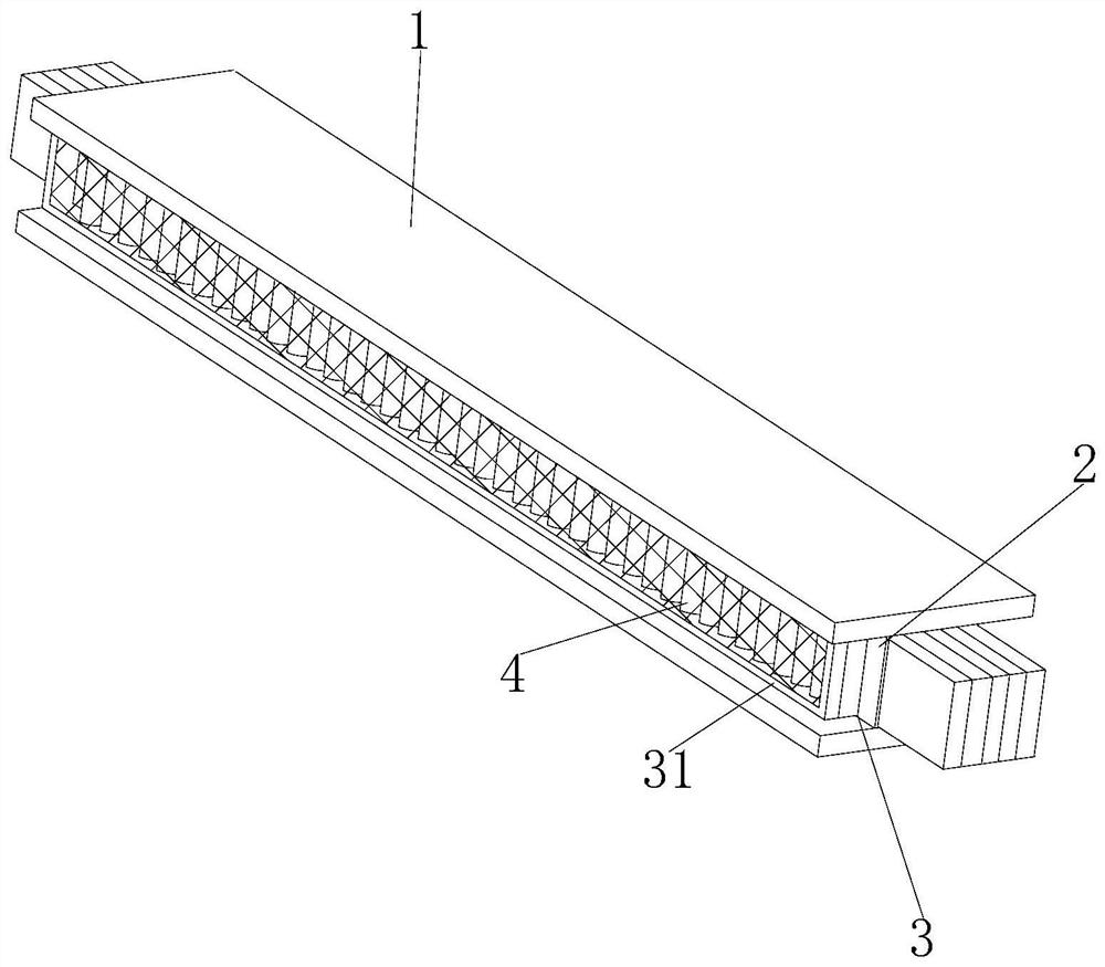
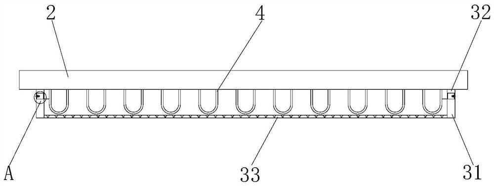
[0027] see Figure 1-6 , the present invention provides the following technical solutions: a hollow grounding insulation-intensive busway, including a cover plate 1, the two sides of the cover plate 1 are connected with side plates 2, and the side walls of the side plate 2 are connected with several U-shaped tubular The heat sink 4 is provided with a dust-proof assembly 3 on the side wall of the side plate 2 and on the periphery of the U-shaped tubular heat sink 4;

[0028] The dust-proof assembly 3 includes a mounting frame 31, a fixed frame 32 and a dust-proof net 33. On the side wall of the side plate 2 and at the periphery of the U-shaped tubular heat sink 4, a fixed frame 32 is connected, and the fixed frame 32 is far away from one side of the side plate 2. An installation frame 31 is arranged on the side, and a dustproof net 33 is connected to the inner side wall of the installation frame 31 .

[0029] Specifically, the dustproof assembly 3 also includes a plug block 34...

Embodiment 2

[0035] The difference between this embodiment and Embodiment 1 is that a drying assembly 5 is provided inside the cover plate 1 and the side plate 2, the drying assembly 5 includes a drying bag 52 and a desiccant 57, and the inside of the cover plate 1 and the side plate 2 is provided with Drying bag 52, the interior of drying bag 52 is filled with desiccant 57,

[0036] Specifically, the side of the dry pack 52 close to the cover plate 1 and the side plate 2 is provided with an installation box 51, and the installation box 51 and the dry pack 52 are glued together,

[0037] By adopting the above technical solution, it is convenient to insert the dry bag 52 into the inside of the cover plate 1 and the side plate 2 .

[0038] Specifically, the drying assembly 5 also includes a connecting groove 53, a limiting groove 54, a limiting plate 55 and a connecting block 56. The two ends of the installation box 51 are connected with the connecting block 56, and the side wall of the cove...


PUM


Abstract

The invention discloses a hollow grounding insulation intensive bus duct, and belongs to the technical field of bus ducts. The hollow grounding insulation intensive bus duct comprises a cover plate, the two sides of the cover plate are connected with side plates, the side walls of the side plates are connected with a plurality of U-shaped tubular cooling fins, and dustproof assemblies are arranged on the side walls of the side plates and located on the peripheries of the U-shaped tubular cooling fins; and the dustproof assembly comprises a mounting frame, a fixing frame and a dustproof net, the fixing frame is connected to the side wall of the side plate and located on the periphery of the U-shaped tubular cooling fin, and the mounting frame is arranged on the side, away from the side plate, of the fixing frame. According to the invention, the mounting frame, the fixed frame, the dustproof net, the plugging block, the spring, the through hole, the connecting column, the fixed ring, the movable plate, the groove, the plugging groove and other structures are arranged, and under the mutual cooperation of the structures, the dustproof function can be realized, and the situation that dust and other impurities in the external environment adhere to the U-shaped tubular cooling fins and affect the cooling effect of the U-shaped tubular cooling fins is avoided.

Description

technical field [0001] The invention belongs to the technical field of bus ducts, and in particular relates to a hollow grounding insulation-intensive bus duct. Background technique [0002] The busway is a closed metal device composed of copper and aluminum busbar columns, which is used to distribute large power to various components of the decentralized system. It has increasingly replaced wires and cables in indoor low-voltage power transmission trunk line projects. [0003] Chinese patent application No. 201922303941.3 discloses a compact and dense fire-resistant bus duct. In the device, several U-shaped tubular heat sinks are connected to the side wall of the side plate. During use, impurities such as dust in the external environment adhere to the on the U-shaped tubular heat sink, it is easy to affect the heat dissipation effect of the U-shaped tubular heat sink, and it is not easy to clean; in addition, when the moisture in the external environment enters the inside ...

Claims


Application Information

Patent Timeline
Patent Type & Authority Applications(China)
IPC IPC(8): H02G5/06H02G5/10
CPCH02G5/06H02G5/10
Inventor 马见雄
Owner ZHENJIANG GARDERMOEN INTELLIGENT POWER TECH CO LTD
Why Eureka
Try Eureka