
Miniature circuit breaker

A technology for small circuit breakers and circuit breakers, which is applied in the direction of protective switch terminals/connection, protective switch operation/release mechanism, etc., and can solve problems such as cumbersomeness, potential safety hazards, and affecting the efficiency of maintenance or search or judgment

Pending Publication Date: 2022-01-18
ZHEJIANG CHINT ELECTRIC CO LTD
View PDF0 Cites 0 Cited by
  • Summary
  • Abstract
  • Description
  • Claims
  • Application Information

AI Technical Summary

Problems solved by technology

[0003] 1. The existing circuit breakers are generally installed in the distribution box. When the circuit breaker needs to be repaired or the failed circuit breaker needs to be replaced, the operator needs to check the circuit breaker installed on the circuit step by step, which is cumbersome; especially for plug-in circuit breakers As far as circuit breakers are concerned, they are generally installed in cabinets with a large number of installations. It takes a lot of time and energy to overhaul, replace faulty circuit breakers, find a specific circuit breaker, or judge the status of a circuit breaker, which affects the maintenance or search. or the efficiency of judgment, and there are certain security risks
[0004] 2. When the circuit breaker is used on some specific equipment with small space, there are defects such as inability to install or high installation cost
[0005] 3. The signal output component of the circuit breaker can only output a single type of signal, which cannot meet the demand; and the installation reliability of the signal output component is low

Method used


Image

  • Miniature circuit breaker
  • Miniature circuit breaker
  • Miniature circuit breaker

Examples


Embodiment Construction

[0051] The following is attached Figure 1-30 The given examples further illustrate the specific implementation of the miniature circuit breaker of the present invention. The miniature circuit breaker of the present invention is not limited to the description of the following embodiments.

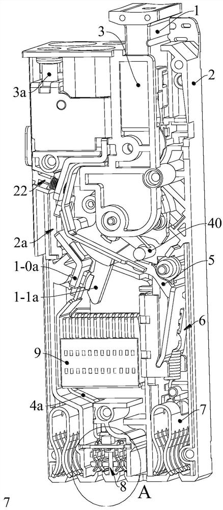
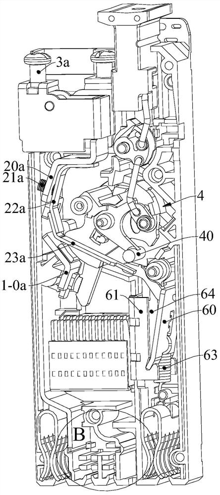
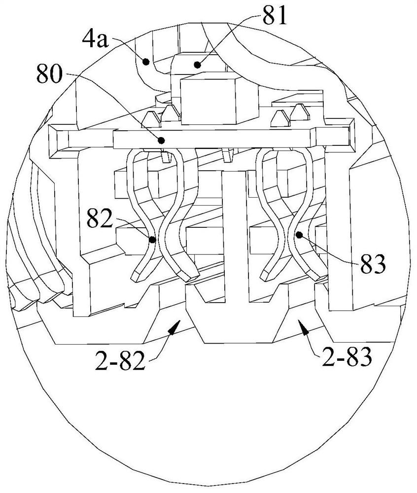
[0052] Such as figure 1 , 2 As shown in , 5, 14, and 26, the miniature circuit breaker of the present invention includes a circuit breaker case 2 and an operation button 1, and an operating mechanism 4 respectively arranged in the circuit breaker case 2, moving contacts 1-1a and static contacts used in conjunction Head 1-0a, arc extinguishing chamber 9, overload protection mechanism 2a and short circuit protection mechanism 6; the operation button 1 is arranged at one end of the circuit breaker casing 2, and one end of the operation button 1 is inserted in the circuit breaker casing 2 and connected with the circuit breaker casing 2 sliding fit; the operation button 1 is driven and connec...


PUM


Abstract

The invention relates to the field of low-voltage electric appliances, in particular to a miniature circuit breaker. The circuit breaker comprises a circuit breaker shell, an overload protection mechanism arranged in the circuit breaker shell, a moving contact, a static contact and an operating mechanism; the overload protection mechanism is in driving fit with the operating mechanism, and the moving contact is in driving connection with the operating mechanism; the overload protection mechanism comprises a first current-conducting plate, a first connecting plate and a bimetallic strip. The two ends of the first connecting plate are connected with the first current-conducting plate and the bimetallic strip respectively. The bimetallic strip is connected with the first conductive plate through a first flexible connection and is connected with the static contact through a second flexible connection. A third flexible connection is selectively arranged between the first conductive plate and the static contact. According to the miniature circuit breaker, the overload protection mechanism can be used for protection of overload current of more specifications.

Description

technical field [0001] The invention relates to the field of low-voltage electrical appliances, in particular to a small circuit breaker. Background technique [0002] The use of circuit breakers can effectively improve the safety of electrical equipment and has been widely used. However, most existing circuit breakers have the following problems: [0003] 1. The existing circuit breakers are generally installed in the distribution box. When the circuit breaker needs to be repaired or the failed circuit breaker needs to be replaced, the operator needs to check the circuit breaker installed on the circuit step by step, which is cumbersome; especially for plug-in circuit breakers As far as circuit breakers are concerned, they are generally installed in cabinets with a large number of installations. It takes a lot of time and energy to overhaul, replace faulty circuit breakers, find specific circuit breakers, or judge the status of circuit breakers, which affects the maintenanc...

Claims


Application Information

Patent Timeline
IPC IPC(8): H01H71/16H01H71/08
CPCH01H71/16H01H71/08
Inventor 杨帆卢科军葛伟骏杨安顾翔翼顾斌斌
Owner ZHEJIANG CHINT ELECTRIC CO LTD
Learn More