Wall splicing mechanism for fabricated building

A prefabricated and architectural technology, which is applied in building construction, building material processing, construction, etc., can solve the problems of time-consuming and laborious splicing, inconvenient installation and disassembly, and affecting the use of walls, etc., to reduce gaps and facilitate operation and use Fast and improve the efficiency of splicing

Pending Publication Date: 2022-01-14
CHINA 22MCC GROUP CORP
View PDF0 Cites 3 Cited by
  • Summary
  • Abstract
  • Description
  • Claims
  • Application Information

AI Technical Summary

Problems solved by technology

[0002] Buildings assembled from prefabricated components on site are called prefabricated buildings. According to the form and construction method of prefabricated components, they are divided into five types: block building, plate building, box building, skeleton plate building and rising plate building. Type, in the splicing process of the existing prefabricated wall, it needs to be spliced ​​by screws, etc., and additional tools are required for installation. It is not convenient to install and disassemble, and it takes time and effort to splice. In the middle, gaps are easy to appear between the walls, and the gaps between the walls cannot be solved well, and the gaps will affect the normal use of the walls

Method used


Image

  • Wall splicing mechanism for fabricated building
  • Wall splicing mechanism for fabricated building
  • Wall splicing mechanism for fabricated building

Examples


Embodiment Construction

[0016] The present invention will be further described below in conjunction with the examples, the purpose is only to better understand the contents of the present invention, therefore, the examples given do not limit the protection scope of the present invention.

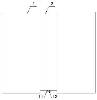
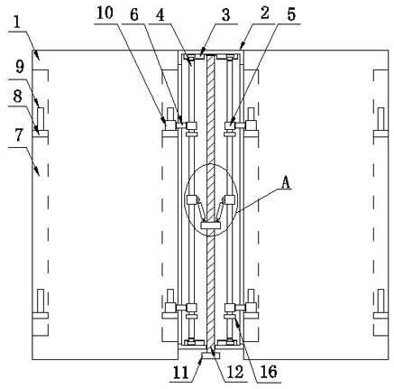
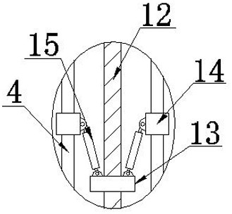
[0017] see Figure 1-Figure 3 , a wall splicing mechanism for prefabricated buildings, including two wall panels 1, a splicing frame 2 located between the two wall panels 1, a chute plate 3, a sliding rod 4, a sliding sleeve 5, a connecting rod 6, Chute 7, fixed plate 8, clamp rod 9, ferrule 10, rotating plate 11, threaded rod 12, internal threaded bearing 13, connecting sleeve 14, support rod 15, baffle plate 16, splicing frame 2 cavity top and bottom Corresponding chute 7 plates 3 are respectively arranged on both sides, and the sliding rod 4 is slidably connected between the two chute 7 plates 3 on the same side through a slider. The top and bottom of the sliding rod 4 are respectively covered with sliding sleev...


PUM


Abstract

The invention relates to the technical field of fabricated buildings, in particular to a wall splicing mechanism for a fabricated building. The wall splicing mechanism comprises a sliding rod and a connecting rod, corresponding sliding groove plates are arranged on the two sides of the top and the two sides of the bottom of an inner cavity of a splicing frame correspondingly, the sliding rod is slidably connected between the two sliding groove plates on the same side through sliding blocks, the top and the bottom of the sliding rod are sleeved with sliding sleeves correspondingly, and sliding grooves are formed in the two sides of a wallboard correspondingly; and fixing plates are arranged at the top and the bottom of an inner cavity of a sliding groove, clamping rods are arranged on the fixing plates, one end of the connecting rod is connected with a sliding sleeve, a clamping sleeve matched with the clamping rods is arranged at the other end of the connecting rod, and a stretching assembly is arranged between a connecting frame and the wallboard. According to the wall splicing mechanism for the fabricated building, the two wallboards and the splicing frame can be quickly spliced and mounted, other tools such as screws are not needed, operation and use are more convenient and faster, the splicing efficiency of the two wallboards and the splicing frame is greatly improved, and a gap between the two wallboards can be reduced.

Description

technical field [0001] The invention relates to the technical field of prefabricated buildings, in particular to a wall splicing mechanism for prefabricated buildings. Background technique [0002] Buildings assembled from prefabricated components on site are called prefabricated buildings. According to the form and construction method of prefabricated components, they are divided into five types: block building, plate building, box building, skeleton plate building and rising plate building. Type, in the splicing process of the existing prefabricated wall, it needs to be spliced ​​by screws, etc., and additional tools are required for installation. It is not convenient to install and disassemble, and it takes time and effort to splice. In the middle, there are gaps between the walls easily, and the gaps between the walls cannot be solved well, and the gaps will affect the normal use of the walls. Contents of the invention [0003] The present invention aims to solve the ...

Claims


Application Information

Patent Timeline
IPC IPC(8): E04B1/343E04B1/38E04B1/61E04G21/14
CPCE04B1/34315E04B1/34321E04B1/34384E04B1/38E04B1/6108E04G21/14
Inventor 杨毛毛周晓丽
Owner CHINA 22MCC GROUP CORP
Why Eureka
Try Eureka