
Automatic adhesive tape installation equipment for building components

A technology for automatic installation and building components, applied in metal processing equipment, metal processing, manufacturing tools, etc., can solve the problems of unsightly appearance, product quality decline, low production efficiency, etc., to reduce labor and labor, improve the quality of tube bundles, The effect of improving production efficiency

Active Publication Date: 2022-01-14
泰德阳光(浙江)建筑科技集团有限公司
View PDF7 Cites 0 Cited by
  • Summary
  • Abstract
  • Description
  • Claims
  • Application Information

AI Technical Summary

Problems solved by technology

However, the accuracy of manual operation and cutting machine is not high, so that the length of the cut rubber strips is different, there are errors, or the end of the rubber strips is cut obliquely and unevenly, which makes the overall quality of the product decline, and the appearance is not beautiful. Bring a bad impression to customers and affect the sales of the management team
During assembly, it is also inconvenient to cooperate between the rubber strip and the tube bundle. Generally, there are bent parts on both sides of the rubber strip. The bent part needs to be broken apart and put on both sides of the tube bundle. The efficiency is very low, and a lot of labor is required every time the tube bundle is assembled, which is time-consuming and laborious

Method used


Image

  • Automatic adhesive tape installation equipment for building components
  • Automatic adhesive tape installation equipment for building components
  • Automatic adhesive tape installation equipment for building components

Examples


Embodiment Construction

[0033]In the description of the present invention, it should be noted that for orientation words, such as the term "center", "horizontal (X)", "longitudinal (Y)", "vertical (Z)", "length", " Width", "Thickness", "Top", "Bottom", "Front", "Back", "Left", "Right", "Vertical", "Horizontal", "Top", "Bottom", "Inner ", "outside", "clockwise", "counterclockwise" and other indication orientations and positional relationships are based on the orientation or positional relationship shown in the drawings, and are only for the convenience of describing the present invention and simplifying the description, rather than indicating or implying the Means that a device or element must have a specific orientation, be constructed and operated in a specific orientation should not be construed as limiting the specific protection scope of the present invention.

[0034] In addition, terms such as "first" and "second" are used for descriptive purposes only, and cannot be understood as indicating or...


PUM


Abstract

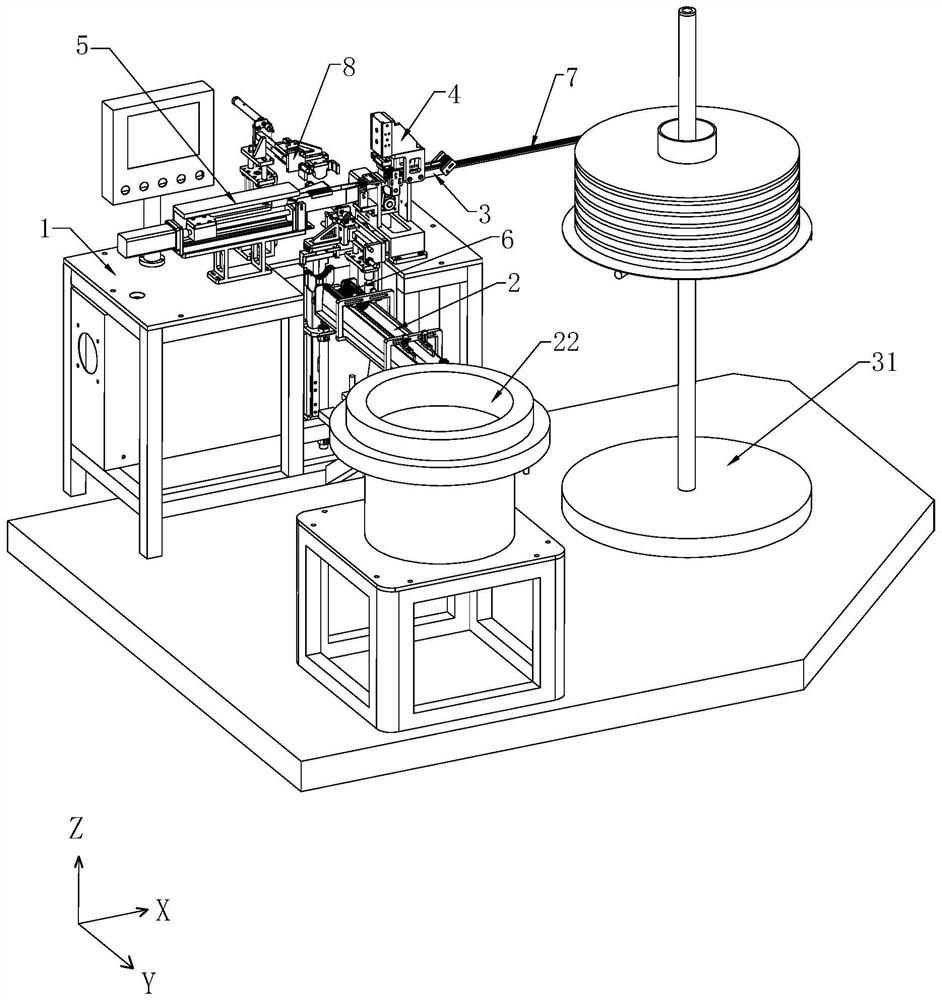
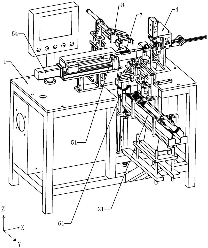
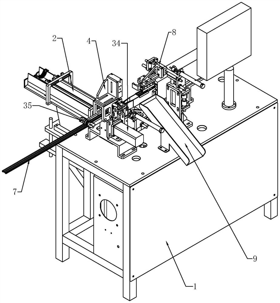
The invention discloses automatic adhesive tape installation equipment for building components. The equipment comprises a feeding guide rail, an adhesive tape feeding component, an adhesive tape cutting component and an assembling component, wherein tube bundles are neatly arranged on the feeding guide rail, a movable feeding clamp is arranged above the feeding guide rail, and the feeding clamp is used for clamping the tube bundles and transferring the tube bundles to a tube bundle tool; the adhesive tape feeding component comprises a driving wheel and a driven wheel which are matched with each other, and an adhesive tape is located between the driving wheel and the driven wheel; the adhesive tape cutting component comprises a material distributing groove plate and a cutter capable of moving up and down, and the cutter can penetrate through the material distributing groove plate to cut off the adhesive tape; and the assembling component comprises a movable pneumatic claw, the pneumatic claw can grab the adhesive tape to move the adhesive tape to the position over the tube bundle tool, and the tube bundle tool upwards moves the tube bundles to be assembled with the adhesive tape. The adhesive tape is automatically installed through a machine, the production efficiency is greatly improved, the cut-off length of the adhesive tape is controlled through a first servo motor, all the adhesive tapes are consistent in length, accurate and attractive, and the quality of the assembled tube bundles is greatly improved.

Description

technical field [0001] The invention relates to the field of adhesive strip installation equipment, in particular to an automatic installation adhesive strip equipment for building components. Background technique [0002] The rubber strip clamp in the building components is composed of tube bundles and rubber strips. Two semicircular tube bundles are fixed into a circular clamp by bolts, and the rubber strips are installed inside the tube bundles. The rubber strips in the tube bundle are manually assembled. Before assembly, the length of the rubber strips is usually confirmed according to the size of the tube bundle. The rubber strips can be cut manually or with a simple machine. However, the precision of manual operation and cutting machine is not high, so that the lengths of the cut rubber strips are different, there are errors, or the end of the rubber strips is cut obliquely and unevenly, which reduces the overall product quality and looks unattractive. Bring bad impre...

Claims


Application Information

Patent Timeline
IPC IPC(8): B23P19/04B26D1/08B26D5/12B26D7/06
CPCB23P19/04B26D1/08B26D5/12B26D7/06
Inventor 贾军强褚晴涛胡佳敏
Owner 泰德阳光(浙江)建筑科技集团有限公司
Learn More