
Zipper tooth clamping device for zipper production

A clamping device, zipper technology, applied in the application, sliding fastener elements, fasteners, etc., can solve the problems of low work efficiency, reduced processing volume, affecting processing efficiency, etc., and achieves convenient operation, simple structure, and processing. Fast and efficient results

Pending Publication Date: 2022-01-14
杭州罗松贸易有限公司
View PDF0 Cites 0 Cited by
  • Summary
  • Abstract
  • Description
  • Claims
  • Application Information

AI Technical Summary

Problems solved by technology

[0004] The object of the present invention is to provide a zipper tooth clamping device for zipper production, to solve the problem in the above background technology that the zipper teeth need to be clamped at the edge of the cloth when the current zipper is being produced. A single stamping and clamping process is adopted, and at the same time, the clamping process can only be completed by placing the zipper teeth one by one in the designated feeding hole position, which makes the work efficiency low and the amount of processing is greatly reduced, which cannot meet the current market needs. , human participation is still required when fixing the fabric, so that it can be tightly set at the designated position, so that the zipper teeth can be fastened to the edge position, which also affects the efficiency of processing

Method used


Image

  • Zipper tooth clamping device for zipper production
  • Zipper tooth clamping device for zipper production
  • Zipper tooth clamping device for zipper production

Examples


Embodiment Construction

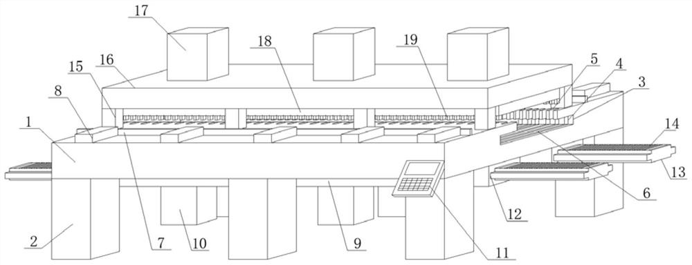
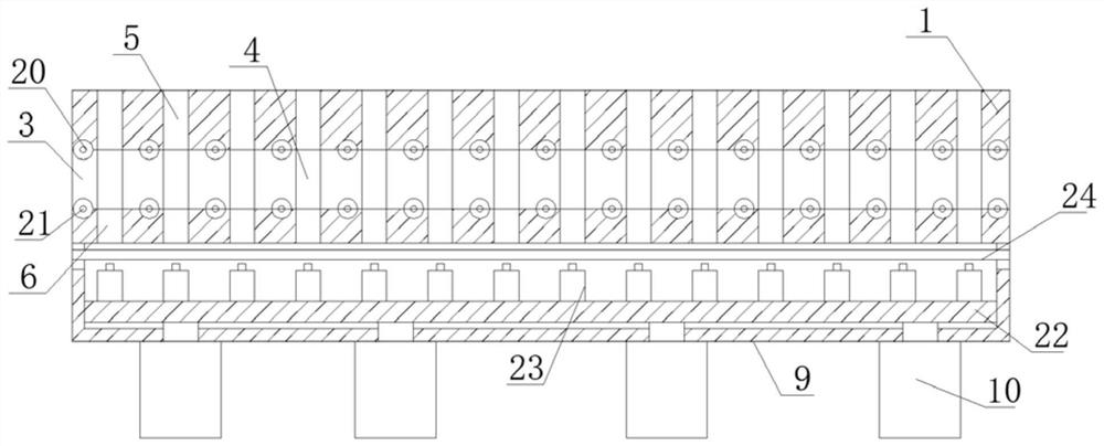
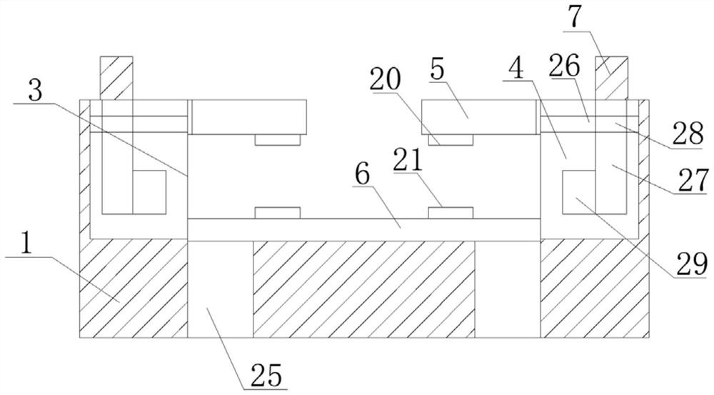
[0027] see Figure 1-2, in an embodiment of the present invention, a zipper tooth clamping device for zipper production includes a bottom support plate 1, the bottom surface of the bottom support plate 1 is welded vertically downward with a support pole 2, and the top surface of the bottom support plate 1 is horizontally provided with Top feeding chute 3, the inner side of the top feeding chute 3 is provided with a through slot 4, the number of supporting vertical rods 2 is multiple, and the multiple supporting vertical rods 2 are arranged in parallel with each other, and the multiple supporting vertical rods 2 are arranged parallel to each other. The top of the rod 2 is vertically welded on the bottom surface of the bottom support plate 1 near the edge, the top feed trough 3 is horizontally set at the midline position of the top surface of the bottom support plate 1, and the two ends of the top feed trough 3 run through the bottom support plate 1 horizontally The two sides of...


PUM


Abstract

The invention discloses a zipper tooth clamping device for zipper production, and relates to the field of zipper production, the zipper tooth clamping device comprises a bottom supporting plate, a supporting vertical rod is vertically and downwards welded to the bottom surface of the bottom supporting plate, a top conveying groove is horizontally formed in the top surface of the bottom supporting plate, and a through groove hole is formed in the inner side edge of the top conveying groove, matched top grooves are evenly formed in the top face of the bottom supporting plate, bottom through grooves are horizontally and evenly formed in the bottom face of the inner side of the top conveying groove, a pushing and pressing transverse plate is in butt joint with the top face of the bottom supporting plate, a pushing and pressing air cylinder is horizontally connected to the top face of the bottom supporting plate through bolts, and a bottom sleeving box is horizontally welded to the bottom face of the bottom supporting plate, and the bottom surface of the bottom sleeving box is in bolted connection with a top connection air cylinder. According to the device, the integrated structure is designed, the structure is simple, operation is convenient, machining is faster and more efficient by adopting a double material conveying structure, meanwhile, batch clamping treatment can be conducted at a time through machining integration, and the zipper production efficiency is greatly improved.

Description

technical field [0001] The invention relates to the technical field of zipper production, in particular to a zipper tooth clamping device for zipper production. Background technique [0002] The zipper has developed from the original metal material to the non-metallic material, from a single variety with a single function to a multi-species multi-specification comprehensive function. It has undergone a long evolution process from a simple structure to today's exquisite, beautiful and colorful. The little zipper is playing an increasingly important role in people's lives, showing its importance and vitality more and more. [0003] For the production of the current zipper, the zipper teeth need to be clamped at the edge of the fabric. The traditional method is to use a single stamping and clamping process, and at the same time place the zipper teeth one by one in the designated feeding hole position. The clamping process can only be completed, which makes the work efficiency ...

Claims


Application Information

Patent Timeline
Patent Type & Authority Applications(China)
IPC IPC(8): A44B19/48
CPCA44B19/48
Inventor 陈广林
Owner 杭州罗松贸易有限公司
Learn More