
Chirped pulse compression device and laser

A compression device and chirped pulse technology, which is applied in the direction of lasers, laser components, phonon exciters, etc., can solve the problems of large size, high cost, and low utilization rate of the grating area, and achieve performance improvement, cost saving, Effect of high pulse energy

Pending Publication Date: 2022-01-07
深圳市欧凌镭射科技有限公司
View PDF0 Cites 2 Cited by
  • Summary
  • Abstract
  • Description
  • Claims
  • Application Information

AI Technical Summary

Problems solved by technology

[0003] The purpose of the embodiments of the present application is to provide a chirped pulse compression device to solve the technical problems of low grating area utilization, large size and high cost in the chirped pulse compression device in the prior art

Method used


Image

  • Chirped pulse compression device and laser
  • Chirped pulse compression device and laser
  • Chirped pulse compression device and laser

Examples


Embodiment Construction

[0029] In order to make the technical problems, technical solutions and beneficial effects to be solved by the present application clearer, the present application will be further described in detail below in conjunction with the accompanying drawings and embodiments. It should be understood that the specific embodiments described here are only used to explain the present application, and are not intended to limit the present application.

[0030] It should be noted that when an element is referred to as being “fixed” or “disposed on” another element, it may be directly on the other element or be indirectly on the other element. When an element is referred to as being "connected to" another element, it can be directly connected to the other element or indirectly connected to the other element.

[0031] It should also be noted that the orientation terms such as left, right, up and down in the embodiments of the present application are only relative concepts or refer to the norm...


PUM


Abstract

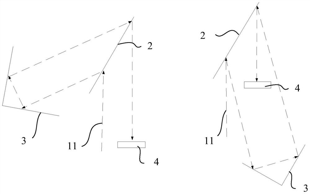
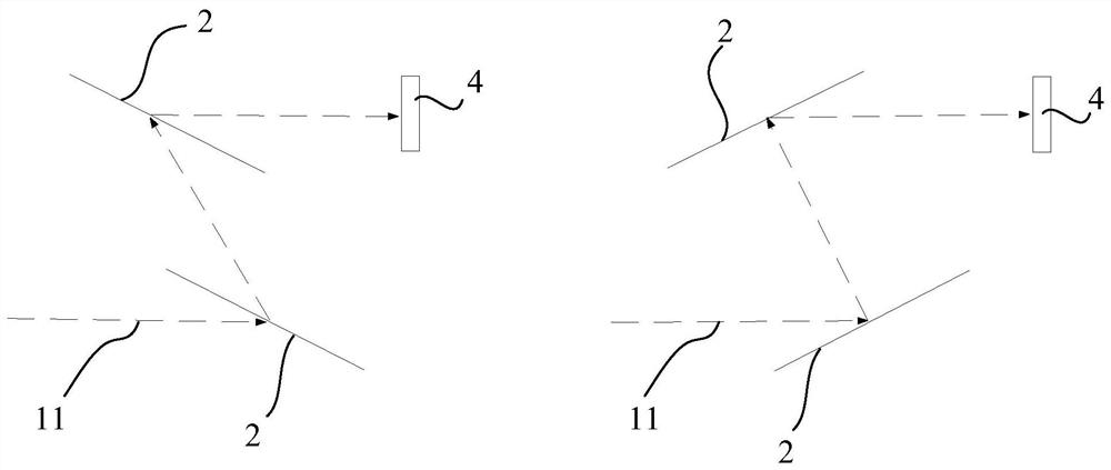
The invention provides a chirped pulse compression device and a laser. The chirped pulse compression device comprises the following components: a translation roof prism and a grating which are spaced oppositely, wherein all angles are arranged in a total reflection manner; and a reflector assembly which comprises a plurality of reflectors which are all located between the grating and the translation roof prism; wherein after incident light is emitted to the grating, the incident light is diffracted by the grating to form first light which is emitted to the reflector assembly along a first direction, and the first light is reflected back to the reflector assembly after being reflected by the reflector assembly for multiple times and translated by the reference surface position of the translational roof prism, and then is reflected for many times; and the light returns and enters the grating along the direction symmetrical with the first direction relative to the normal direction, and then is subjected to secondary diffraction by the grating to form a second light meeting the grating diffraction condition. The chirped pulse compression device provided by the invention can improve the utilization rate of the grating region and increase the compressible pulse width so as to improve the pulse output single pulse energy and reduce the cost.

Description

technical field [0001] This application belongs to the technical field of laser devices, and more specifically relates to a chirped pulse compression device and a laser. Background technique [0002] At present, ultrafast lasers with high power and high pulse energy reaching the femtosecond or picosecond level are widely used in precision micromachining, biomedical and scientific research fields due to their narrow pulse width, large single pulse energy, and high repetition rate. . In order to obtain ultrafast lasers with high power and large pulse energy, chirped pulse amplification technology (Chirped Pulse Amplification, CPA) is usually used in the industry. This technology first expands the seed pulse width to the level of hundreds of picoseconds or nanoseconds, increases the average power through the amplification stage, and then further compresses the pulse width to the level of femtoseconds or picoseconds through the chirped pulse compression device. Here, the exten...

Claims


Application Information

Patent Timeline
Patent Type & Authority Applications(China)
IPC IPC(8): H01S3/1055H01S3/125H01S3/00
CPCH01S3/0057H01S3/125H01S3/1055
Inventor 李云亭吴朝辉谢晓华吴光辉陈乐岳超瑜
Owner 深圳市欧凌镭射科技有限公司
Learn More