A self-pressing film antenna deployment mechanism
An unfolding mechanism and self-compressing technology, which is applied in the direction of folding antennas, etc., can solve the problems of easy bending, instability, and inability to maintain the compressed state of the skeleton, and achieve the effect of ensuring reliability
- Summary
- Abstract
- Description
- Claims
- Application Information
AI Technical Summary
Problems solved by technology
Method used
Image
Examples
Embodiment 1
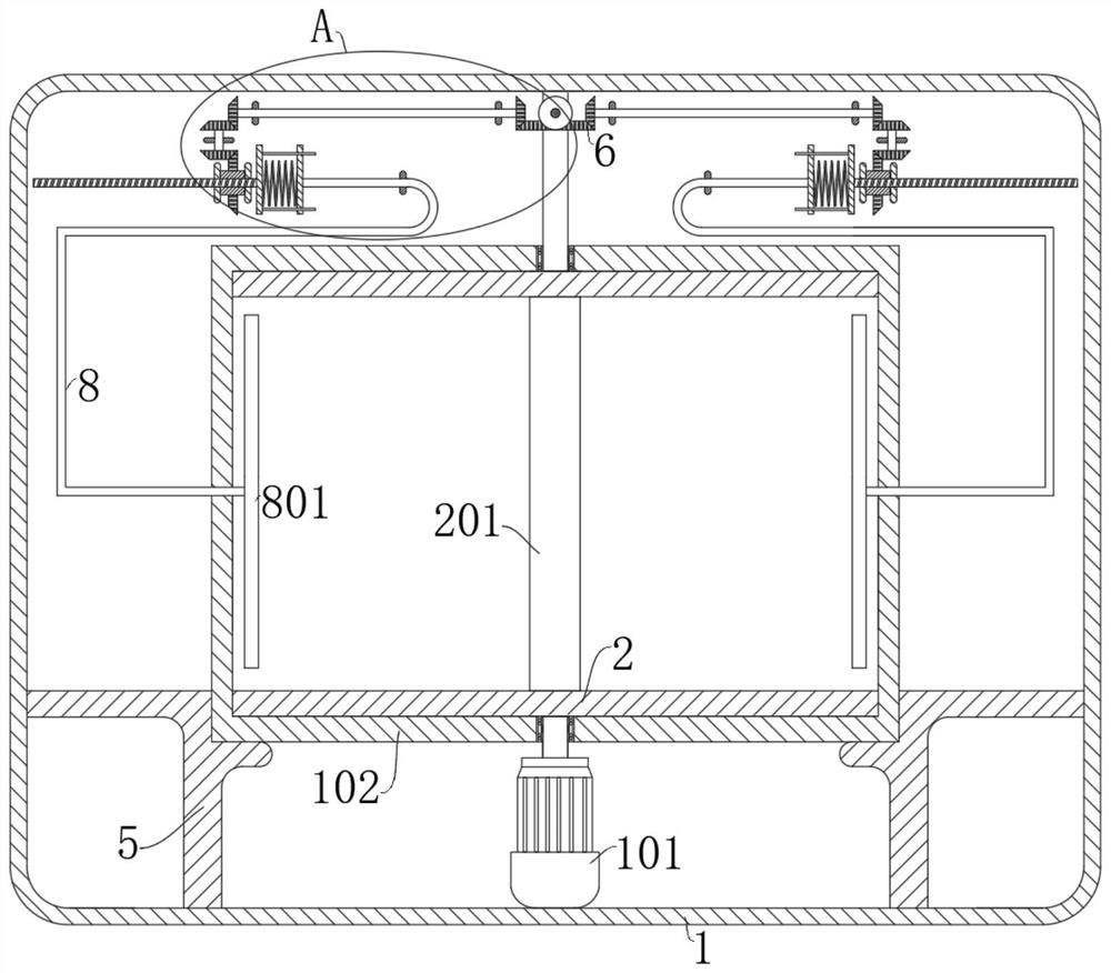
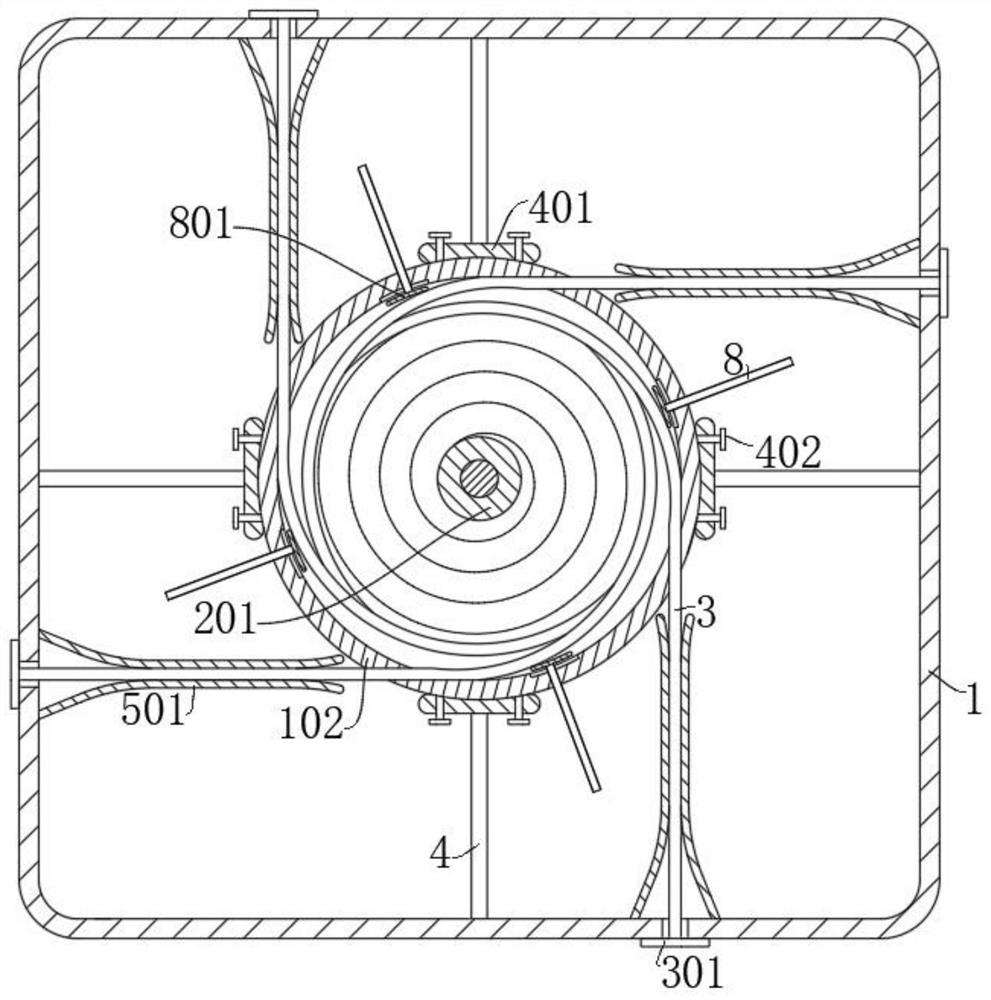
[0032] refer to Figure 1-8 , a self-compressing type film antenna deployment mechanism, including a box body 1 and a reel 102, the reel 102 is fixed in the box 1, the reel 102 is a hollow cylinder, and also includes: a motor 101, connected In the box body 1, the output end of the motor 101 is fixedly connected with the retracting shaft 201, and the retracting shaft 201 is located in the retracting drum 102 and is in line with the axis of the retracting drum 102; the extension arm 302, one end of the extension arm 302 is fixed On the retracting drum 102 and wound on the side wall of the retracting shaft 201, the film antenna body 3 is fixed on the skeleton formed by the extension arm 302; The skeleton composed of 302 runs through the retracting groove 202; the moving rod 8 is slidably connected to the side wall of the retracting drum 102, and the end of the moving rod 8 extending to the inside of the retracting drum 102 is connected with a compression device for maintaining th...
Embodiment 2
[0041] refer to Figure 1-8 , on the basis of Example 1, further,
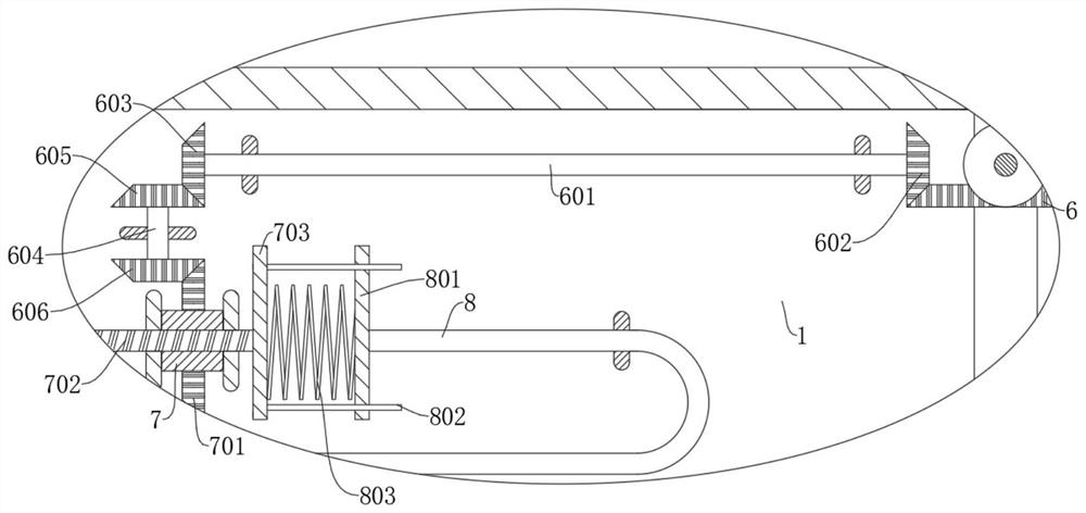
[0042] This embodiment discloses a pushing mechanism. The pushing mechanism includes a first rotating shaft 601 and a threaded rod 702. The first rotating shaft 601 is rotatably connected in the box body 1. The output end of the motor 101 extends out of the take-up shaft 201 and one end is fixedly connected with First bevel gear 6, one end of the first rotating shaft 601 is fixedly connected with the second bevel gear 602 meshed with the first bevel gear 6, and the end of the first rotating shaft 601 away from the second bevel gear 602 is fixedly connected with the third bevel gear 603 The second rotating shaft 604 and the threaded sleeve 7 are also rotatably connected in the box body 1, and one end of the second rotating shaft 604 is fixedly connected with the fourth bevel gear 605 meshed with the third bevel gear 603, and the second rotating shaft 604 is far away from the fourth bevel gear. One end of the g...
Embodiment 3
[0049] refer to Figure 1-8 , on the basis of Example 2, further,
[0050] The end of the threaded rod 702 close to the moving rod 8 is fixedly connected with the first voltage stabilizing plate 703, the end of the moving rod 8 away from the pressing part is fixedly connected with the second stabilizing plate 801, and the side wall of the first stabilizing plate 703 is fixedly connected with a guide The rod 802 and the guide rod 802 are slidably connected to the second pressure stabilizing disk 801 , and a voltage stabilizing spring 803 is also connected between the first voltage stabilizing disk 703 and the second pressure stabilizing disk 801 .
[0051] During the moving process of the threaded rod 702, the transmission force is transmitted to the moving rod 8 through the pressure stabilizing spring 803 to drive the moving rod 8 to move.
[0052] The elasticity of the pressure stabilizing spring 803 can effectively prevent the pressing part from moving suddenly and causing ...
PUM
 Abstract
Description
Claims
Application Information
 - R&D
- Intellectual Property
- Life Sciences
- Materials
- Tech Scout
- Unparalleled Data Quality
- Higher Quality Content
- 60% Fewer Hallucinations
Browse by: Latest US Patents, China's latest patents, Technical Efficacy Thesaurus, Application Domain, Technology Topic, Popular Technical Reports.
© 2025 PatSnap. All rights reserved.Legal|Privacy policy|Modern Slavery Act Transparency Statement|Sitemap|About US| Contact US: help@patsnap.com


