
Dynamic detection-based marking device for sponge city engineering

A dynamic detection, sponge city technology, applied to the device for coating liquid on the surface, cleaning method using tools, mechanical thickness measurement, etc., can solve the problems of plate compaction, waste of time, and inability to automatically clean the dust on the plate. , to achieve the effect of preventing markup confusion and avoiding confusion

Pending Publication Date: 2022-01-07
王涵
View PDF0 Cites 1 Cited by
  • Summary
  • Abstract
  • Description
  • Claims
  • Application Information

AI Technical Summary

Problems solved by technology

[0003] However, as far as the current detection and marking devices for materials used in traditional urban engineering are concerned, first of all, although the existing devices can also be equipped with some distance detection structures during detection, when the thickness of the plate is too high, it will be blocked by an object similar to a gear bar. In order to realize the detection, but the efficiency of this detection method is low, because when the plate is pushed forward, it will inevitably be blocked when the plate is unqualified. At this time, the unqualified plate needs to be taken out so that the rear plate can continue to be tested. , which is a waste of time; secondly, the existing device cannot realize the detection of the two situations of too low thickness and too high thickness at the same time; finally, the existing device cannot automatically clean the dust on the plate during the detection process. During the detection process, the plate is compacted to improve the detection accuracy

Method used


Image

  • Dynamic detection-based marking device for sponge city engineering
  • Dynamic detection-based marking device for sponge city engineering
  • Dynamic detection-based marking device for sponge city engineering

Examples


Embodiment

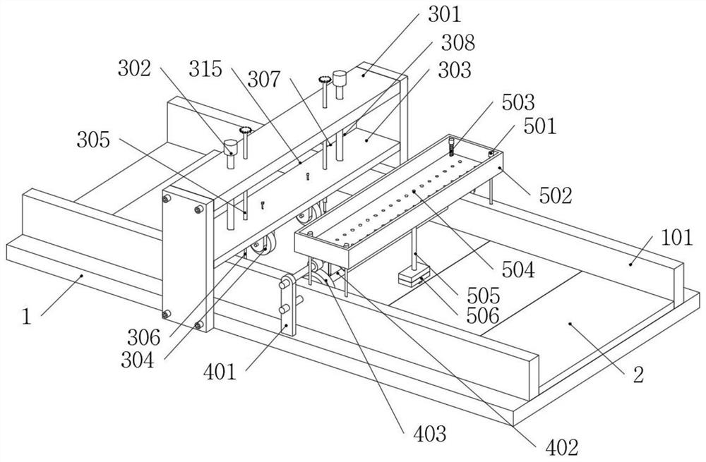
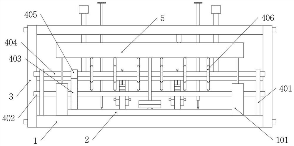
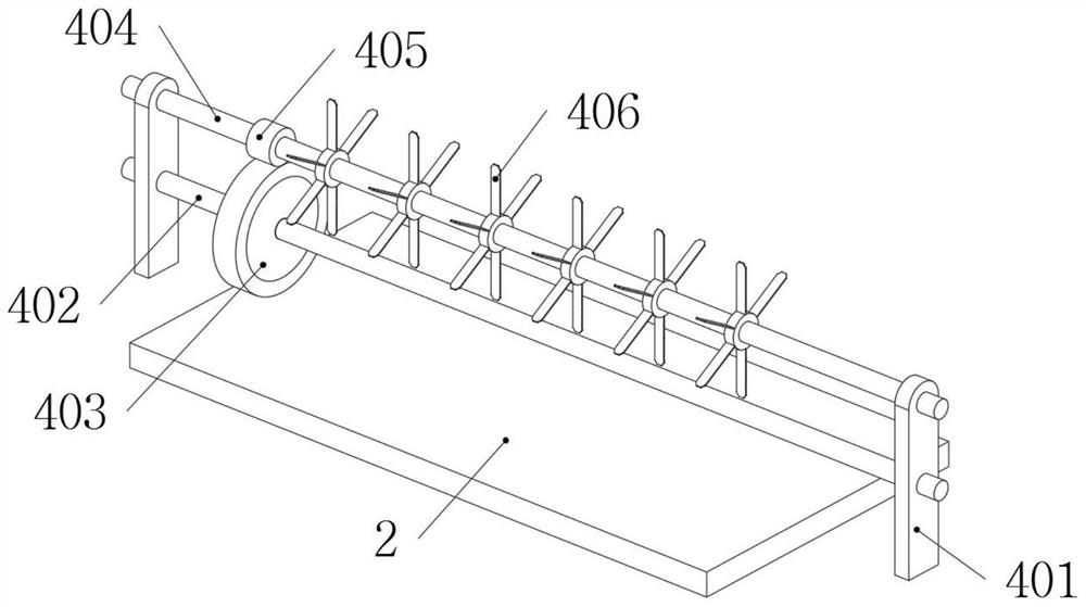
[0045] Example: Please refer to Figure 1 to Figure 9 :

[0046] The present invention proposes a dynamic detection-based marking device for sponge city engineering, including: a main body seat 1, a first marking part 3, a cleaning part 4 and a second marking part 5;

[0047] The main body seat 1 is installed on the workbench through bolts, and two baffle plates 101 are symmetrically welded on the main body seat 1; the plate material 2 is placed in a linear array on the main body seat 1, and the left end surface and the right end surface of the plate material 2 are respectively connected with the two block baffle 101 contact;

[0048] The first marking part 3 is composed of a frame body 301, a sliding rod A302, a mounting seat 303, a roller 304, a threaded rod A305, a marking pen A306, a threaded rod B307, a marking pen B308, a sliding rod B309, a cleaning block 310 and an elastic member B311. And the frame body 301 is fixedly connected to the main body seat 1 by bolts;

[...


PUM


Abstract

The invention provides a dynamic detection-based marking device for sponge city engineering, and relates to the technical field of detection marking devices, wherein the dynamic detection-based marking device comprises a main body seat, a first marking part, a cleaning part and a second marking part; the main body seat is mounted on a workbench through bolts, and two baffles are symmetrically welded on the main body seat; plates are placed on the main body seat in a linear array shape; two rollers are in contact with the top end face of the plate, and a sliding rod A, a mounting seat and the rollers jointly form a plate compaction structure, so that the phenomenon of detection result error caused by non-compaction of the plates can be prevented; and the problems that in an existing device, when the thickness of the plates is too high, the plates are blocked by an object similar to a blocking rod, the detection is realized, but the detection method is relatively low in efficiency, and unqualified plates are inevitably blocked when the plates are pushed to move forwards, so that the unqualified plates need to be taken out at the moment, and the rear plates can be continuously detected are solved.

Description

technical field [0001] The invention relates to the technical field of detection and marking devices, in particular to a dynamic detection-based marking device for sponge city engineering. Background technique [0002] In the process of urban engineering construction, a large amount of wood needs to be used. In order to improve the accuracy of construction, these woods will be tested and marked before use. The main purpose is to screen unqualified wood to prevent the direct use of these unqualified wood from affecting the construction accuracy. However, according to different construction requirements, a certain error is allowed in the current thickness. As long as it does not exceed the error range, it can continue to be used. These errors are often controlled within the range of 0.2cm. If it exceeds this range, it is also a substandard product. [0003] However, as far as the current detection and marking devices for materials used in traditional urban engineering are conc...

Claims


Application Information

Patent Timeline
Patent Type & Authority Applications(China)
IPC IPC(8): G01B5/06B05C5/02B05C11/10B08B1/02B07C5/36
CPCG01B5/06B05C5/02B05C11/10B07C5/361B08B1/20
Inventor 马爱葵王涵刘东乐
Owner 王涵
Learn More