
Clamping device

A clamping device and clamping mechanism technology, applied in sawing machine devices, metal sawing equipment, metal processing equipment, etc., can solve problems such as troublesome use, low production efficiency, inability to automatically adjust, etc., to achieve convenient use, improve quality, The effect of reducing drag

Inactive Publication Date: 2022-01-07
ANHUI POLYTECHNIC UNIV MECHANICAL & ELECTRICAL COLLEGE
View PDF1 Cites 0 Cited by
  • Summary
  • Abstract
  • Description
  • Claims
  • Application Information

AI Technical Summary

Problems solved by technology

[0002] Ordinary profile long material sawing machine clamps the product by both sides during production, only one profile long material can be clamped at a time, and only one profile long material can be sawed, and only one product can be sawed out with one saw, and the production efficiency is low , equipment capable of processing multiple long pieces has appeared in the prior art, such as the clamping device and processing equipment disclosed in the patent CN110170841A, which can cut at least two long pieces at one time
[0003] However, the design of patent CN110170841A also contains many deficiencies. For example, when clamping a cylindrical workpiece, it uses a fixed block with a circular groove to fix it, which cannot be automatically adjusted according to the diameter of the workpiece. Every time the diameter of the workpiece changes Both need to manually replace the fixed block, which is very troublesome to use

Method used


Image

  • Clamping device
  • Clamping device
  • Clamping device

Examples


Embodiment Construction

[0021] The following will clearly and completely describe the technical solutions in the embodiments of the present invention with reference to the accompanying drawings in the embodiments of the present invention. Obviously, the described embodiments are only some of the embodiments of the present invention, not all of them. Based on the embodiments of the present invention, all other embodiments obtained by persons of ordinary skill in the art without making creative efforts belong to the protection scope of the present invention.

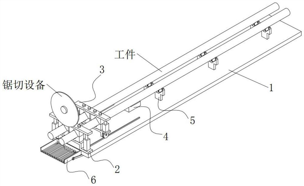
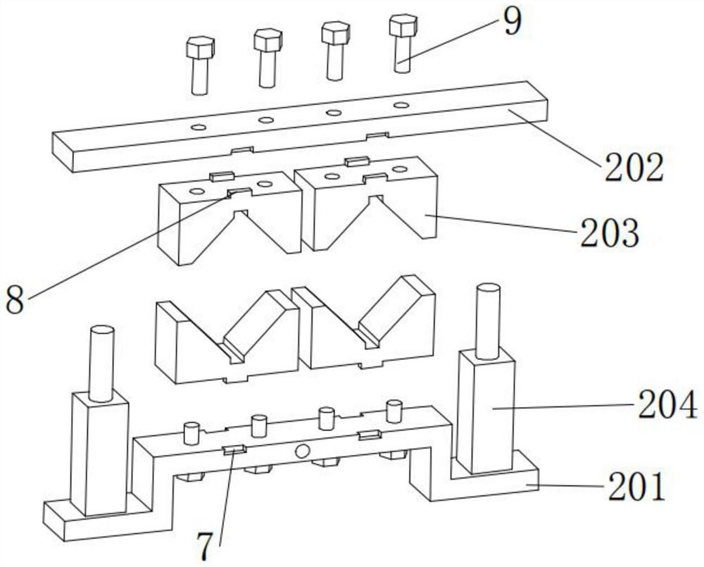
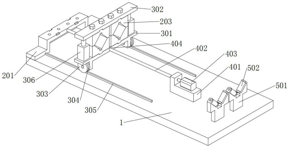
[0022] Such as Figure 1 to Figure 4 As shown, a clamping device includes a base plate 1, and one end of the base plate 1 is provided with a clamping mechanism 2, and the clamping mechanism 2 includes a lower bracket one 201 and an upper bracket one 202, and the lower bracket one 201 and the upper bracket one 202 The upper bracket one 202 is provided with a number of V-shaped blocks 203 corresponding to the upper and lower positions one by one, t...


PUM


Abstract

The invention provides a clamping device, and relates to the technical field of long material machining. The clamping device comprises a bottom plate, one end of the bottom plate is provided with an installing and clamping mechanism, the bottom plate is further provided with a clamping mechanism and a driving mechanism, the clamping mechanism clamps workpieces when the installing and clamping mechanism loosens the workpieces, and the workpieces are dragged to move to complete feeding under drive of the driving mechanism; supporting mechanisms are further arranged on the bottom plate and are arranged at the rear end of the driving mechanism, and the plurality of supporting mechanisms are evenly arranged according to the length of the workpieces so as to support the workpieces; and a collecting mechanism is arranged at the end of the bottom plate and used for collecting the machined workpieces and conveying the workpieces out. The clamping device has the advantages that the multiple workpieces can be clamped at a time, so that the multiple workpieces can be machined at a time by saw cutting equipment, the clamping device can automatically complete feeding of the workpieces, the feeding precision is high, and the processed products are stable in treatment.

Description

technical field [0001] The invention relates to the technical field of long material processing, in particular to a clamping device. Background technique [0002] Ordinary profile long material sawing machine clamps the product by both sides during production, only one profile long material can be clamped at a time, and only one profile long material can be sawed, and only one product can be sawed out with one saw, and the production efficiency is low In the prior art, equipment capable of processing multiple long pieces has appeared, such as the clamping device and processing equipment disclosed in the patent CN110170841A, which can cut at least two long pieces at one time. [0003] However, the design of patent CN110170841A also contains many deficiencies. For example, when clamping a cylindrical workpiece, it uses a fixed block with a circular groove to fix it, which cannot be automatically adjusted according to the diameter of the workpiece. Every time the diameter of th...

Claims


Application Information

Patent Timeline
Patent Type & Authority Applications(China)
IPC IPC(8): B23D47/04
CPCB23D47/04B23D47/042
Inventor 蒋昭
Owner ANHUI POLYTECHNIC UNIV MECHANICAL & ELECTRICAL COLLEGE
Learn More