
Iron core plastic-coated structure with conductive contact pin and manufacturing method of iron core plastic-coated structure

A core and pin technology, which is applied in the manufacture of stator/rotor body, magnetic circuit shape/style/structure, electrical components, etc., can solve problems such as inability to meet application requirements, and achieve a simple and scientific preparation method, which is conducive to manufacturing and molding. Effect

Pending Publication Date: 2022-01-04
东莞市琦祥五金科技有限公司
View PDF0 Cites 0 Cited by
  • Summary
  • Abstract
  • Description
  • Claims
  • Application Information

AI Technical Summary

Problems solved by technology

[0002] Most of the plastic-coated structures of stator cores on the market are three-pin structures, and the pin structures are all non-conductive insulating pins. With the demand for the application and development of stator cores in motor structures, some motors with special structures are in use. When the stator core is applied, it needs to be applied to the conductive pins, so the traditional stator core overmolding structure cannot meet the application requirements in the market

Method used


Image

  • Iron core plastic-coated structure with conductive contact pin and manufacturing method of iron core plastic-coated structure
  • Iron core plastic-coated structure with conductive contact pin and manufacturing method of iron core plastic-coated structure
  • Iron core plastic-coated structure with conductive contact pin and manufacturing method of iron core plastic-coated structure

Examples


Embodiment Construction

[0016] The technical solutions in the embodiments of the present application will be clearly and completely described below in conjunction with the accompanying drawings in the embodiments of the present application. Obviously, the described embodiments are only part of the embodiments of the present application, not all of them, and should be It is understood that the present application is not limited by the example embodiments disclosed and described herein. Based on the embodiments in this application, all other embodiments obtained by persons of ordinary skill in the art without making creative efforts belong to the scope of protection of this application.

[0017] In describing the present invention, it is to be understood that the terms "length", "width", "upper", "lower", "front", "rear", "left", "right", "vertical", The orientation or positional relationship indicated by "horizontal", "top", "bottom", "inner", "outer", etc. is based on the orientation or positional re...


PUM

PropertyMeasurementUnit
thicknessaaaaaaaaaa

Abstract

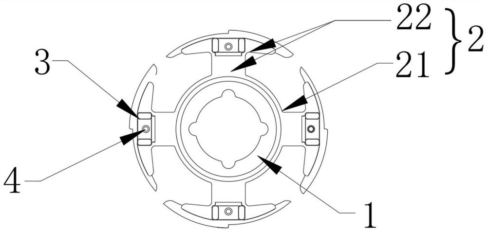
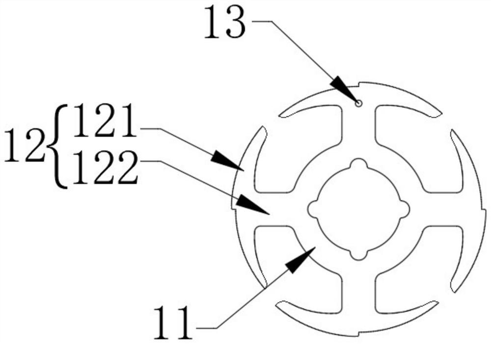
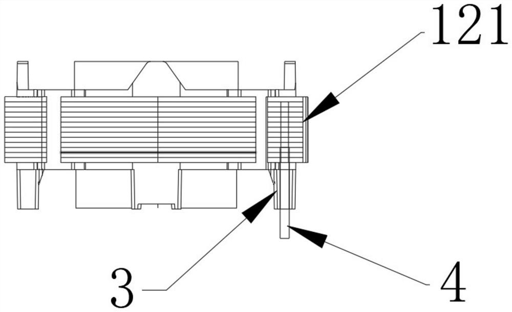
The invention provides an iron core plastic-coated structure with a conductive pin and a manufacturing method thereof. The iron core comprises an integrally formed inner ring iron core and four sections of outer ring iron cores uniformly formed on the periphery of the inner ring iron core; the T-shaped structure outside the outer ring iron core comprises a connecting section connected with the side wall of the inner ring iron core and an outer ring section formed at the tail end of the connecting section, and the inner arc surface of the outer ring section is connected with the connecting section; the wrapping body comprises an inner ring body wrapping the upper and lower end faces of the inner ring iron core and an outer ring body wrapping the inner cambered surface of the outer ring section of the upper and lower end areas of the connecting section in the outer ring iron core; one end face, corresponding to the connecting section, of the outer ring body is provided with a protruding contact pin column, the four contact pin columns are provided with contact pin holes, a contact pin is inserted into each contact pin hole, three contact pins are insulating contact pins, and one contact pin is a conductive contact pin, so the effect of the conductive contact pins is achieved on the iron core plastic-coated structure, so that the special application requirements after the application development of the stator iron core of the motor structure are met.

Description

technical field [0001] The invention belongs to the technical field of motors, and relates to an iron core plastic-wrapped structure with conductive pins and a manufacturing method thereof. Background technique [0002] Most of the plastic-coated structures of stator cores on the market are three-pin structures, and the pin structures are all non-conductive insulating pins. With the demand for the application and development of stator cores in motor structures, some motors with special structures are in use. When the stator core is applied, it needs to be applied to the conductive pins, so the traditional plastic-coated structure of the stator core cannot meet the application requirements in the market. Contents of the invention [0003] In order to achieve the above object, the present invention adopts the following technical solutions: [0004] A theme, including: an iron core and a cladding body, the iron core includes: an integrally formed inner ring iron core and fou...

Claims


Application Information

Patent Timeline
Patent Type & Authority Applications(China)
IPC IPC(8): H02K1/12H02K1/18H02K15/02
CPCH02K1/12H02K1/18H02K15/02H02K2213/03
Inventor 陈学丰
Owner 东莞市琦祥五金科技有限公司
Learn More