Hidden circuit knob switch device of lamp and control mode thereof

A technology of knob switch and control method, which is applied in the field of lamps and lanterns, which can solve the problems of affecting the appearance, limited service life, and inability to directly operate the switch, and achieves the effect of simple structure and long service life of the switch

Pending Publication Date: 2021-12-31
SHENZHEN JING RONG PHOTOELECTRIC TECH
View PDF0 Cites 0 Cited by
  • Summary
  • Abstract
  • Description
  • Claims
  • Application Information

AI Technical Summary

Problems solved by technology

The remote control is for the convenience of turning on or off the lights uniformly. If you want to switch a single candle light, it is most convenient to switch it manually on the light body. The physical switch is usually set at the tail of the light body and the side of the light body. For a certain For some lamps, it is difficult to place them upright when they are installed at the tail of the lamp body. Usually, the recessed switch setting method is used to overcome the defect that it is difficult to place. However, when this structure is placed upright, the switch cannot be directly operated
The other is to set it on the side of the lamp body, which affects the appearance
Whether it is a rear switch or a side switch, more physical switches need to be installed inside the body, and the physical switches are mostly shrapnel type, which has a limited service life

Method used


Image

  • Hidden circuit knob switch device of lamp and control mode thereof
  • Hidden circuit knob switch device of lamp and control mode thereof
  • Hidden circuit knob switch device of lamp and control mode thereof

Examples


Embodiment Construction

[0021] The following will clearly and completely describe the technical solutions in the embodiments of the present invention with reference to the accompanying drawings in the embodiments of the present invention. Obviously, the described embodiments are only some, not all, embodiments of the present invention. Based on the embodiments of the present invention, all other embodiments obtained by persons of ordinary skill in the art without making creative efforts belong to the protection scope of the present invention.

[0022] The present invention takes the LED candle lamp as an example to illustrate the technical solution of the present invention.

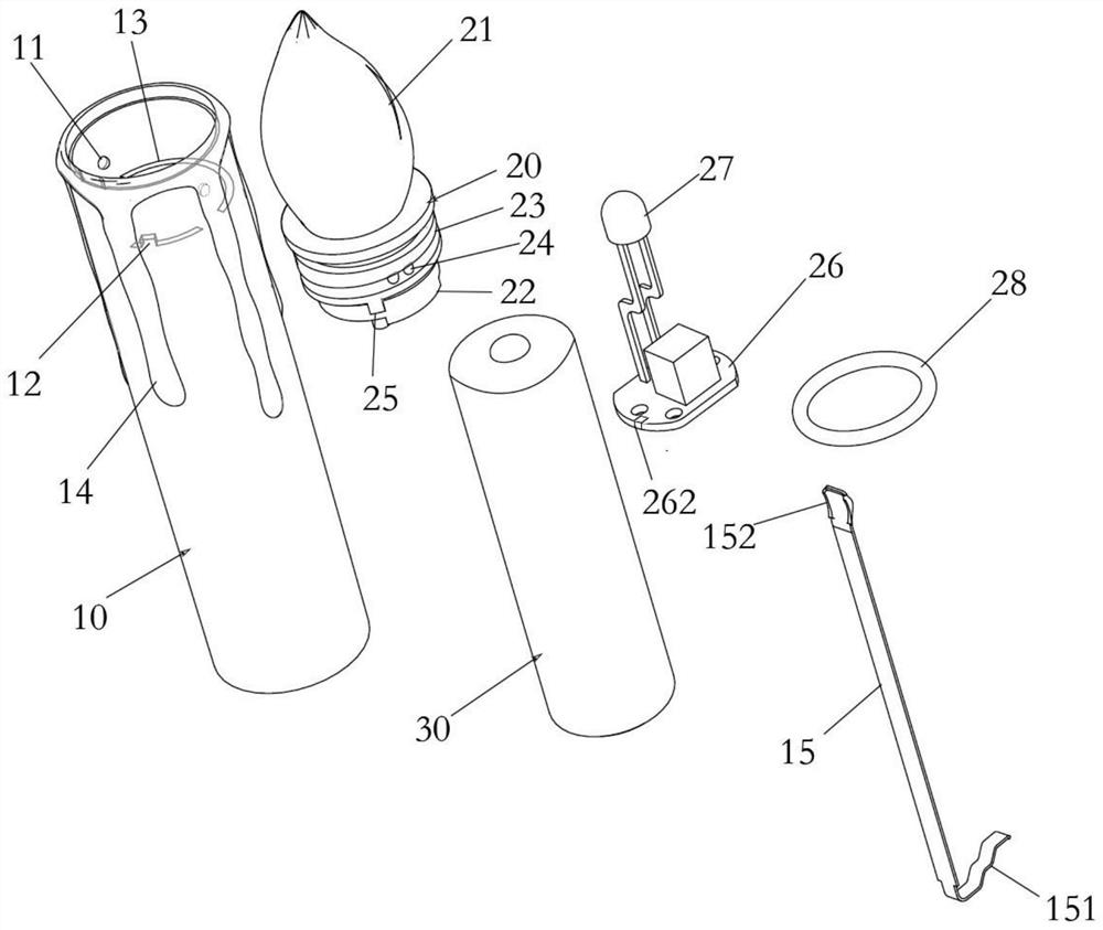
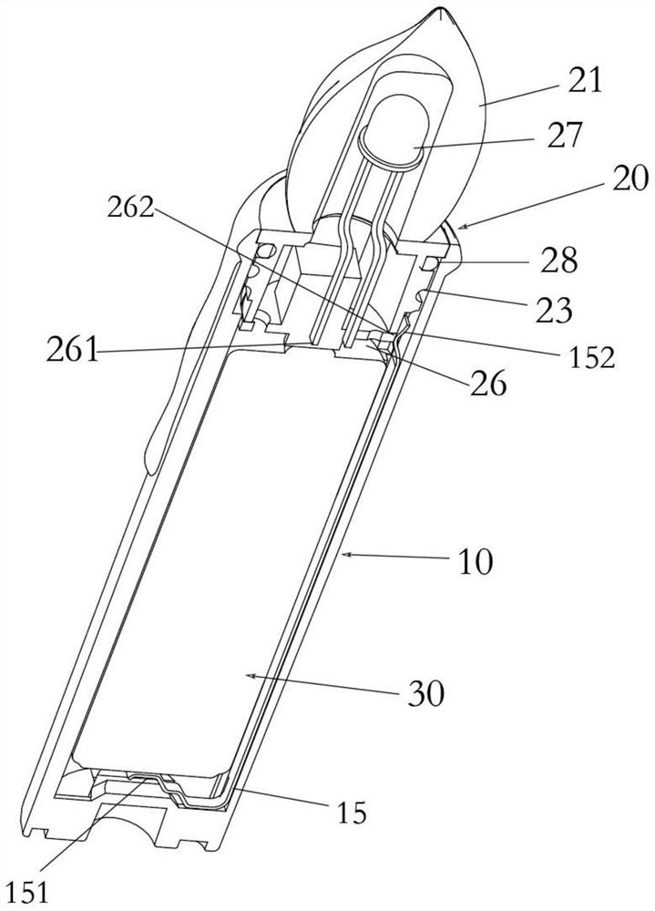
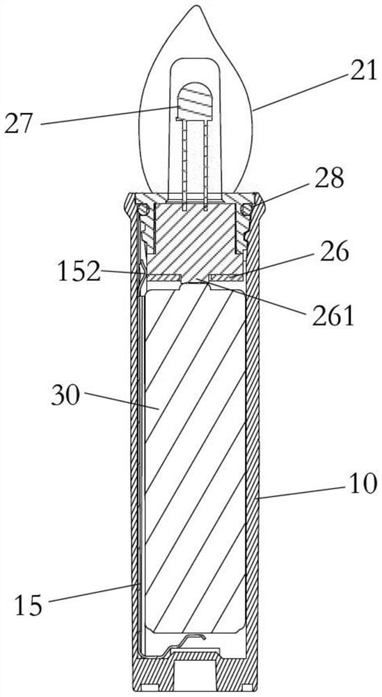
[0023] Such as Figure 1-4 As shown, a hidden circuit knob switch device for an LED candle lamp, the LED candle lamp includes a lamp body 10 and a lamp cap assembly 20, the lamp cap assembly 20 includes a lampshade assembly and a lamp plate, and the lampshade assembly includes an integrally formed lampshade body 21 and The lamp...


PUM


Abstract

The invention discloses a hidden circuit knob switch device of a lamp and a control mode thereof. The lamp comprises a lamp body and a lamp holder assembly, the lamp holder assembly comprises a lampshade assembly and a lamp panel, the lampshade assembly comprises a lampshade body and a lampshade base, and the lampshade base is rotationally connected with the lamp body; the lamp panel is fixed at the bottom end of the lampshade base, the side face of the lampshade base is exposed, the lamp panel forms the bottom face of the lampshade base, a first electrode is arranged at the bottom of the lamp panel, a plurality of second electrodes are arranged on the side edge of the lamp panel, and the first electrode and the second electrodes are connected with a positive electrode and a negative electrode of a control circuit of the lamp panel and used for controlling on or off of a lamp panel circuit. The hidden circuit knob switch device has the advantages that the lamp is turned on and off by rotating the lamp holder, a brand-new switching mode is achieved, and the hidden circuit knob switch device has the advantages of being simple in structure and long in switch service life.

Description

technical field [0001] The invention relates to the field of lamps, in particular to a hidden circuit knob switch device of a lamp and a control method thereof. Background technique [0002] Common portable lamps, such as LED candle lamps, are controlled by a remote controller or have a physical switch on the lamp body. The remote control is for the convenience of turning on or off the lights uniformly. If you want to switch a single candle light, it is most convenient to switch it manually on the light body. The physical switch is usually set at the tail of the light body and the side of the light body. For a certain For some lamps, it is difficult to place them upright when they are arranged at the tail of the lamp body. Usually, a recessed switch setting method is used to overcome the defect that it is difficult to place. However, when this structure is placed upright, the switch cannot be directly operated. The other is to set it on the side of the lamp body, which affe...

Claims


Application Information

Patent Timeline
Patent Type & Authority Applications(China)
IPC IPC(8): F21L4/00F21V23/04F21Y115/10
CPCF21L4/005F21V23/0428F21Y2115/10
Inventor 王文豪刘小琴王庆会
Owner SHENZHEN JING RONG PHOTOELECTRIC TECH
Why Eureka
Try Eureka