
Sliding block and plastic pulling part deformation adjustable separating and inverted buckling mechanism for injection mold

A technology of injection mold and deformation mechanism, which is applied in the field of deformation and undercut mechanism of plastic part with adjustable slider of injection mold. The effect of reducing mold manufacturing costs and improving production efficiency

Pending Publication Date: 2021-12-31
ZHEJIANG KAIHUA MOLDS
View PDF1 Cites 0 Cited by
  • Summary
  • Abstract
  • Description
  • Claims
  • Application Information

AI Technical Summary

Problems solved by technology

[0003] The present invention aims to overcome the problems of the existing plastic parts in the above-mentioned prior art, such as exposed clamping lines, unsightly appearance, and inconvenient detachment, etc., and provides an injection mold adjustable slide block to draw plastic parts deformation and detachment mechanism to realize injection molding. Parts fall off and buckle, avoid clamping line exposure, high product aesthetics; simplify mold structure, reduce mold manufacturing costs, increase mold service life, and improve production efficiency

Method used


Image

  • Sliding block and plastic pulling part deformation adjustable separating and inverted buckling mechanism for injection mold
  • Sliding block and plastic pulling part deformation adjustable separating and inverted buckling mechanism for injection mold
  • Sliding block and plastic pulling part deformation adjustable separating and inverted buckling mechanism for injection mold

Examples


Embodiment 1

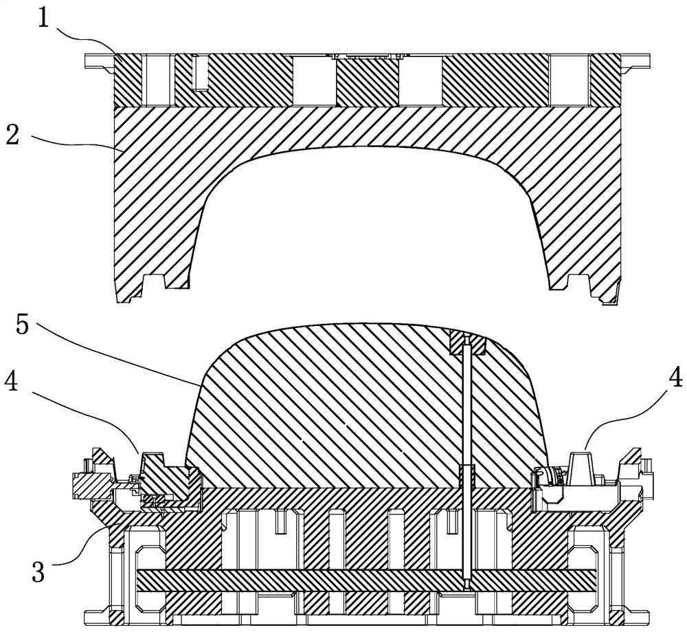
[0032] Such as figure 1 In the shown embodiment 1, an injection mold can adjust the sliding block deformation and undercut mechanism of the stretched plastic part, including the upper doubler plate 1 and the lower doubler plate, wherein the upper doubler plate 1 includes a hot runner plate, and the upper doubler plate 1 There is a cavity 2 connected to the bottom of the doubler plate, the lower doubler plate includes mold feet, a core 3 is connected to the lower doubler plate, an ejector plate is arranged between the core 3 and the lower doubler plate, and a straight ejector rod is arranged on the ejector plate. The straight ejector pin passes through the core 3 .

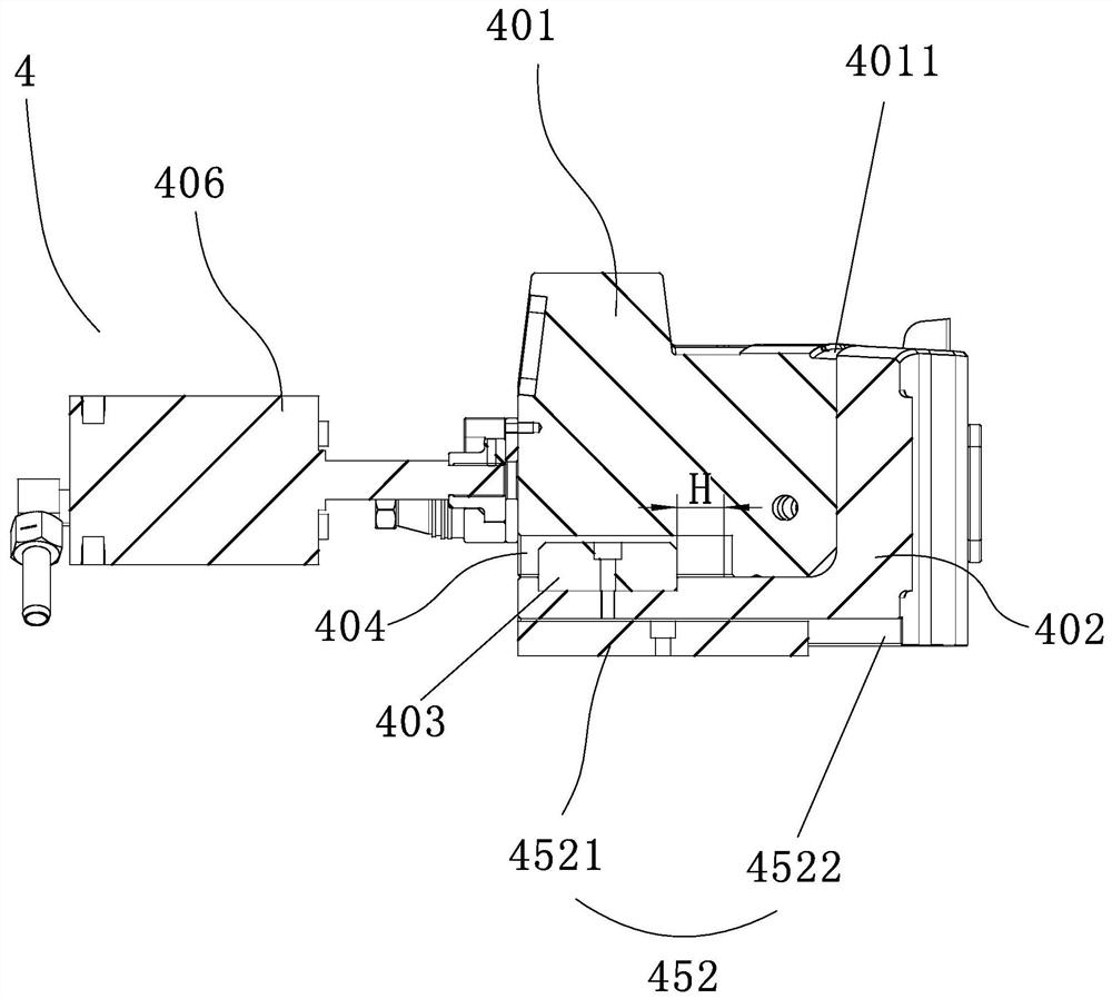
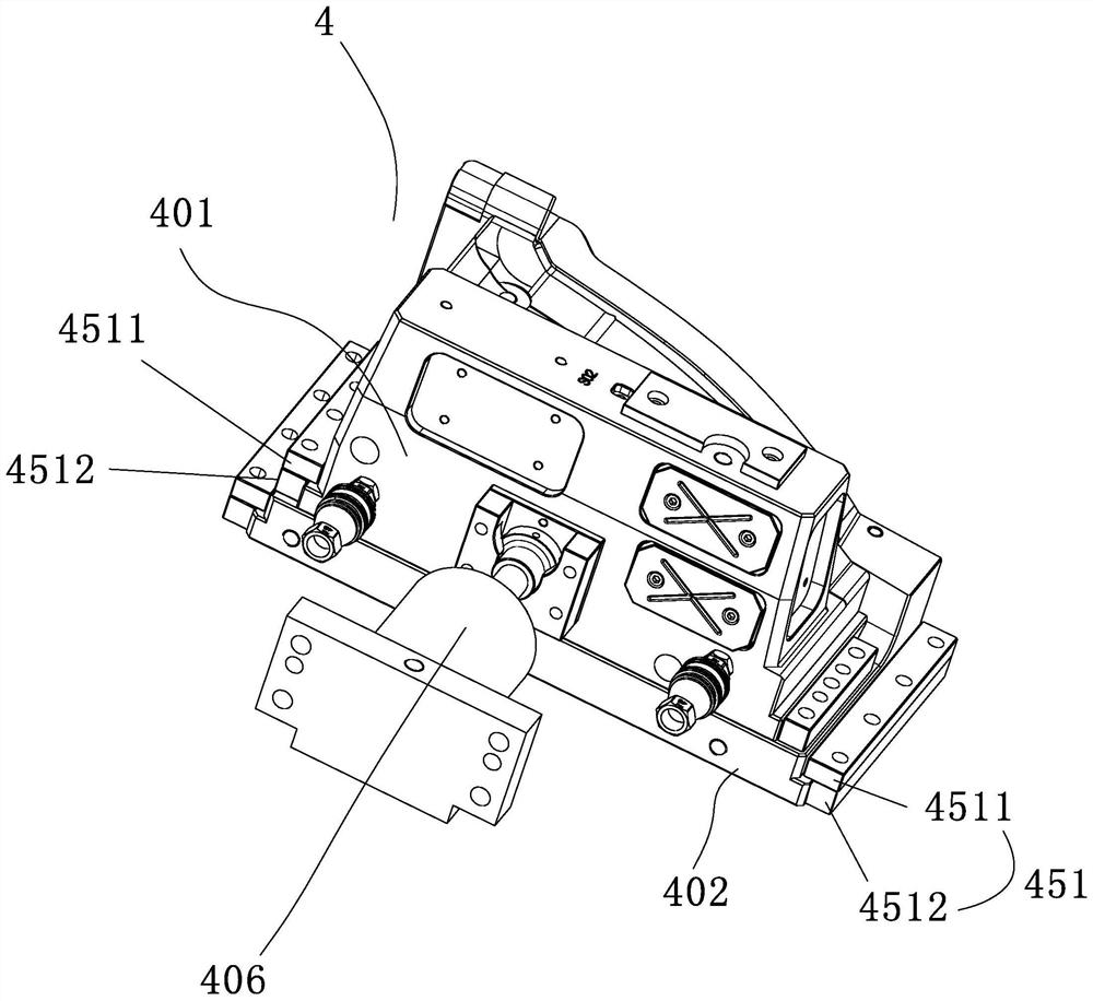
[0033] Such as figure 2 , image 3 As shown, the plastic part deformation mechanism 4 is provided on the core 3, and the plastic part deformation mechanism 4 includes a deformation slider 402 and a driving slider 401, and the driving slider 401 is slidably arranged on the deformation slider 402. The deformation...

Embodiment 2

[0041] The technical solution of embodiment 2 is basically the same as the technical solution of embodiment 1, the difference is that: the limit block 403 is arranged on the driving slider 401, and the limit chute 404 is arranged on the pulling deformation slider 402, in Before the injection molded product 5 is pulled and deformed, a distance is provided between the limit block 403 and the end surface of the limit chute 404 away from the injection molded product 5 .

Embodiment 3

[0043] The technical solution of embodiment 3 is basically the same as the technical solution of embodiment 1, the difference is that: the limiting chute 404 is arranged on the driving slider 401, and the limiting chute 404 extends to a side where the driving slider 401 is away from the product. On the side and communicated with the outside world, such a setting is convenient to cooperate with the first guide structure 451, and slide the driving slider 401 onto the pulling deformation slider 402, which is convenient and quick to install.

[0044] Or the limit chute 404 is arranged on the drawing deformation slider 402, at this time the limit chute 404 extends to the side surface of the drawing deformation slider 402 close to the injection molded product 5 and communicates with the outside world, such setting is also convenient for driving the slider 401 quick installation.


PUM


Abstract

The invention discloses a sliding block and plastic pulling part deformation adjustable separating and inverted buckling mechanism for an injection mold. The mechanism comprises an upper compound plate and a lower compound plate, a mold core is connected to the lower compound plate, plastic pulling part deformation mechanisms used for achieving product deformation are arranged on the mold core, the plastic pulling part deformation mechanisms comprise pulling deformation sliding blocks and driving sliding blocks, the driving sliding blocks are arranged on the pulling deformation sliding blocks in a sliding manner, and the pulling deformation sliding blocks are arranged on the mold core in a sliding manner. According to the sliding block and plastic pulling part deformation adjustable separating and inverted buckling mechanism for the injection mold, separating and inverted buckling of an injection molding part are achieved, clamping wires are prevented from being exposed, and the product attractiveness is high; and the mold structure is simplified, the mold manufacturing cost is reduced, the mold service life is prolonged, and the production efficiency is improved.

Description

technical field [0001] The invention relates to the related technical field of injection molds, in particular to an adjustable sliding block deformation and undercut mechanism for plastic parts of injection molds. Background technique [0002] Due to the needs of assembly, some plastic parts usually have a lot of turning over and overturned, and the requirements for clamping are particularly high, so they cannot be designed according to the traditional method. Usually we will design the outer parting or inner parting design. The outer parting needs the inner design of the large straight top and the enlarged inclined top. With such a structure, when the product is ejected, there are defects such as the exposed clip line and affecting the appearance. The "Elastic Deformation Mechanism for Undercut Elastic Deformation of Injection Mold Plastic Parts" disclosed in the Chinese patent literature, its announcement number CN106393604B, includes upper and lower doubler plates, the u...

Claims


Application Information

Patent Timeline
IPC IPC(8): B29C45/33B29C45/44
CPCB29C45/33B29C45/4407
Inventor 梁正华梁凯林连明王华良
Owner ZHEJIANG KAIHUA MOLDS
Learn More