Image alignment method for video monitoring and unmanned aerial vehicle

A technology for video surveillance and image alignment, applied in image enhancement, image analysis, image data processing, etc., can solve problems such as image coordinate errors, time-consuming and labor-consuming, and coordinate value errors, and achieve precise alignment and improved accuracy.

Active Publication Date: 2021-12-24
广州赋安数字科技有限公司
View PDF7 Cites 0 Cited by
  • Summary
  • Abstract
  • Description
  • Claims
  • Application Information

AI Technical Summary

Problems solved by technology

However, in this method, due to the fact that the manually calibrated coordinates contain errors in practical applications, the obtained image coordinates generally contain errors, which is time-consuming and labor-intensive.

Method used


Image

  • Image alignment method for video monitoring and unmanned aerial vehicle
  • Image alignment method for video monitoring and unmanned aerial vehicle
  • Image alignment method for video monitoring and unmanned aerial vehicle

Examples


Embodiment

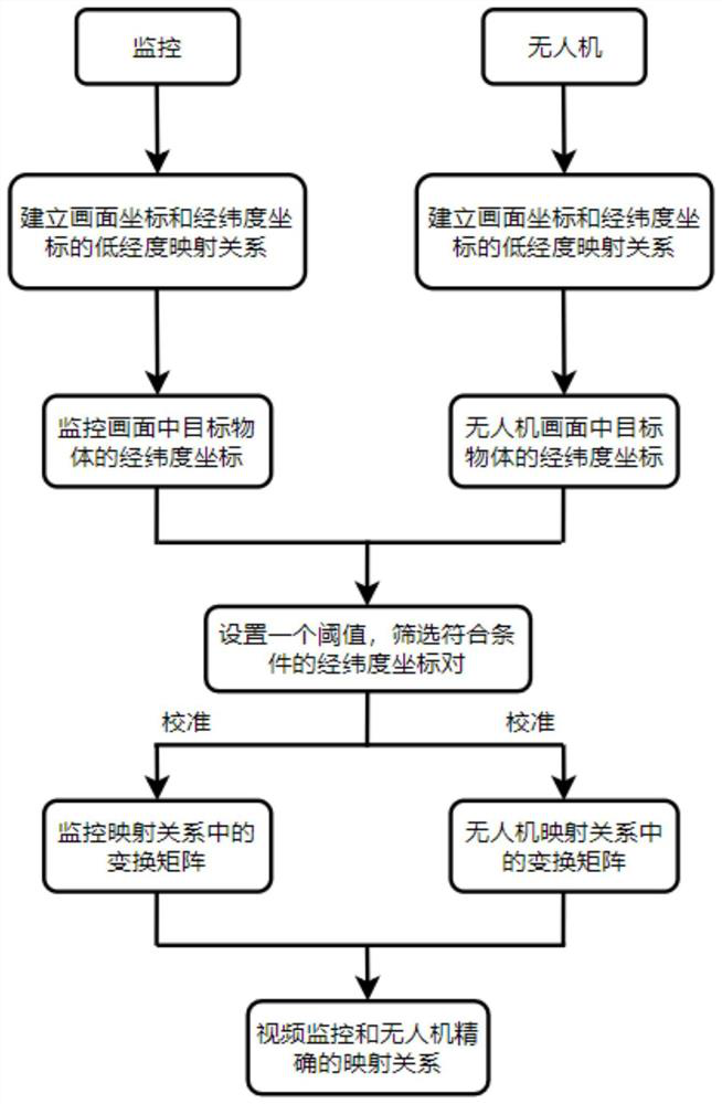
[0089] refer to figure 1 , the present embodiment discloses a method for image alignment of video surveillance and unmanned aerial vehicles, comprising the following steps:

[0090] Step S1: Aligning the coordinates of the monitoring camera screen and the latitude and longitude coordinates, and establishing a low-precision mapping relationship between the screen coordinates of the monitoring camera and the latitude and longitude coordinates;

[0091] Step S2: Align the UAV camera image coordinates with the latitude and longitude coordinates, and establish a low-precision mapping relationship between the UAV camera image coordinates and the latitude and longitude coordinates;

[0092] Step S3: Use the target detection algorithm to detect all objects in the surveillance camera and UAV camera images, obtain the image coordinates of all objects in the surveillance camera and UAV camera images, and obtain the transformed object through the low-precision mapping relationship in step...


PUM


Abstract

The invention discloses an image alignment method for video monitoring and an unmanned aerial vehicle. The method comprises the following steps: S1, aligning the image coordinates and latitude and longitude coordinates of a monitoring camera, and building a low-precision mapping relation between the image coordinates and latitude and longitude coordinates of the monitoring camera; s2, aligning the image coordinates and the latitude and longitude coordinates of the unmanned aerial vehicle camera, and establishing a low-precision mapping relation between the image coordinates and the latitude and longitude coordinates of the unmanned aerial vehicle camera; s3, screening target objects with corresponding positions in the monitoring camera picture and the unmanned aerial vehicle camera picture to obtain a longitude and latitude coordinate pair set K of the mutually corresponding target objects, and taking an average value of each pair of longitude and latitude coordinates as a standard longitude and latitude coordinate of the group, and S4, recalculating two transformation matrixes of the video monitoring and the unmanned aerial vehicle according to the standard latitude and longitude coordinate set in the step S3, and establishing an accurate mapping relationship between the video monitoring and the unmanned aerial vehicle through the transformation matrixes obtained through calculation.

Description

technical field [0001] The invention relates to the field of monitoring and detection, in particular to an image alignment method for video monitoring and unmanned aerial vehicles. Background technique [0002] Video surveillance and unmanned aerial vehicles are widely used in the ocean and land, and can conduct rapid daily monitoring of areas that are illegal or suspected of illegal use of the sea, illegal buildings and other characteristics, providing a basis for illegal use of sea investigations and emergencies. in accordance with. In order to quickly obtain the information of different angles of view of the target object, so as to play a better monitoring role, video surveillance and UAV image mapping are required. [0003] The existing technology generally adopts a method for image alignment to extract feature key points and feature descriptors of two images, and then use a matching algorithm to find feature points with a high matching degree for transformation to achi...

Claims


Application Information

Patent Timeline
Patent Type & Authority Applications(China)
IPC IPC(8): G06T7/70G06K9/32G06F17/16
CPCG06T7/70G06F17/16G06T2207/20068
Inventor 李晓威陈升敬刘晓建
Owner 广州赋安数字科技有限公司
Why Eureka
Try Eureka