Movable workbench for electronic component welding
A technology for electronic components and workbenches, which is applied in welding equipment, auxiliary welding equipment, welding/cutting auxiliary equipment, etc., and can solve problems such as potential safety hazards, shaking and accidental touches, etc.
- Summary
- Abstract
- Description
- Claims
- Application Information
AI Technical Summary
Problems solved by technology
Method used
Image

Examples
Embodiment 1
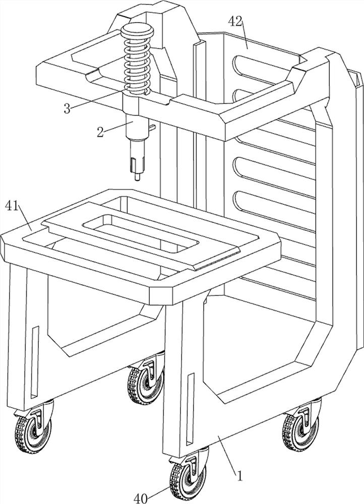
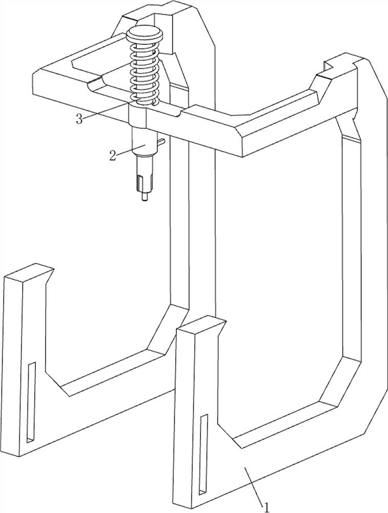
[0026] A mobile workbench for welding electronic components, such as Figure 1 to Figure 4 As shown, it includes a mounting frame 1, a welding torch 2, a first spring 3, a moving mechanism 4 and a pressing mechanism 5. The front side of the mounting frame 1 is slidingly provided with a welding torch 2, and a welding torch 2 is connected between the welding torch 2 and the top of the mounting frame 1. For the first spring 3, a moving mechanism 4 is provided on the outside of the mounting frame 1, and a pressing mechanism 5 is provided at the bottom of the mounting frame 1.
[0027] The moving mechanism 4 includes wheels 40, a workbench 41 and a protective frame 42. The front side of the middle part of the mounting frame 1 is provided with a workbench 41, the rear side of the mounting frame 1 is provided with a protective frame 42, and the left and right sides of the mounting frame 1 bottom are provided with 2 40 wheels.
[0028] Press down mechanism 5 comprises first movable b...
Embodiment 2
[0031] On the basis of Example 1, such as figure 1 , Figure 5 , Image 6 and Figure 7 As shown, a clamping mechanism 6 is also included, and the clamping mechanism 6 includes a first fixed block 60, a second movable block 61, a fourth spring 62, a limit block 63, a third movable block 64, and a first fixed rod 65 and the second movable bar 66, two first fixed blocks 60 are connected to the top rear side of the workbench 41, and the first fixed block 60 tops are all slidingly provided with the second movable block 61, and the bottom of the second movable block 61 is fixed to the first fixed block. A fourth spring 62 is connected between the inner walls of the block 60, and a limit block 63 is provided on the rear side of the top of the workbench 41. The left and right sides of the limit block 63 are slidingly provided with a slide block, and the outside of the rear portion of the slide block is provided with a third movable spring. Block 64, the first fixed rod 65 is symme...
Embodiment 3
[0035] On the basis of Example 2, such as figure 1 , Figure 8 and Figure 9 As shown, an auxiliary mechanism 8 is also included, and the auxiliary mechanism 8 includes a second fixed rod 80, a sixth spring 81, a third movable rod 82 and a sixth movable block 83, and the left and right symmetry of the mounting frame 1 is provided with a second fixed rod 80, a third movable rod 82 is slidably connected between the inner rear side of the second fixed rod 80, a sixth spring 81 is connected between the third movable rod 82 and the rear side of the second fixed rod 80, and the front of the third movable rod 82 A sixth movable block 83 is connected to the side slide type, and the sixth movable block 83 is connected with the welding torch 2 .
[0036] Also include lighting mechanism 9, lighting mechanism 9 includes fixed mount 90, the 7th movable piece 91, the 7th spring 92, the 4th movable rod 93, the 5th movable rod 94 and lighting lamp 95, the left and right sides of the middle ...
PUM
 Abstract
Description
Claims
Application Information
 - Generate Ideas
- Intellectual Property
- Life Sciences
- Materials
- Tech Scout
- Unparalleled Data Quality
- Higher Quality Content
- 60% Fewer Hallucinations
Browse by: Latest US Patents, China's latest patents, Technical Efficacy Thesaurus, Application Domain, Technology Topic, Popular Technical Reports.
© 2025 PatSnap. All rights reserved.Legal|Privacy policy|Modern Slavery Act Transparency Statement|Sitemap|About US| Contact US: help@patsnap.com