
Building ventilation shaft structure with rainproof function

A technology for buildings and ventilation shafts, applied to building structures, building components, buildings, etc., can solve problems such as increased use costs and damage to fans, and achieve the effects of ensuring safe use, reducing use costs, and preventing rainwater from entering

Pending Publication Date: 2021-12-21
江苏天宇设计研究院有限公司
View PDF5 Cites 0 Cited by
  • Summary
  • Abstract
  • Description
  • Claims
  • Application Information

AI Technical Summary

Problems solved by technology

[0003] However, when there is a strong wind on a rainy day, the strong wind will easily blow rainwater into the air shaft channel, which will cause damage to the fans in the air shaft channel and increase the use cost.

Method used


Image

  • Building ventilation shaft structure with rainproof function
  • Building ventilation shaft structure with rainproof function
  • Building ventilation shaft structure with rainproof function

Examples


Embodiment Construction

[0021] The following will clearly and completely describe the technical solutions in the embodiments of the present invention with reference to the accompanying drawings in the embodiments of the present invention. Obviously, the described embodiments are only some, not all, embodiments of the present invention.

[0022] In describing the present invention, it should be understood that the terms "upper", "lower", "front", "rear", "left", "right", "top", "bottom", "inner", " The orientation or positional relationship indicated by "outside", etc. is based on the orientation or positional relationship shown in the drawings, and is only for the convenience of describing the present invention and simplifying the description, rather than indicating or implying that the referred device or element must have a specific orientation, so as to Specific orientation configurations and operations, therefore, are not to be construed as limitations on the invention.

[0023] refer to Figure ...


PUM


Abstract

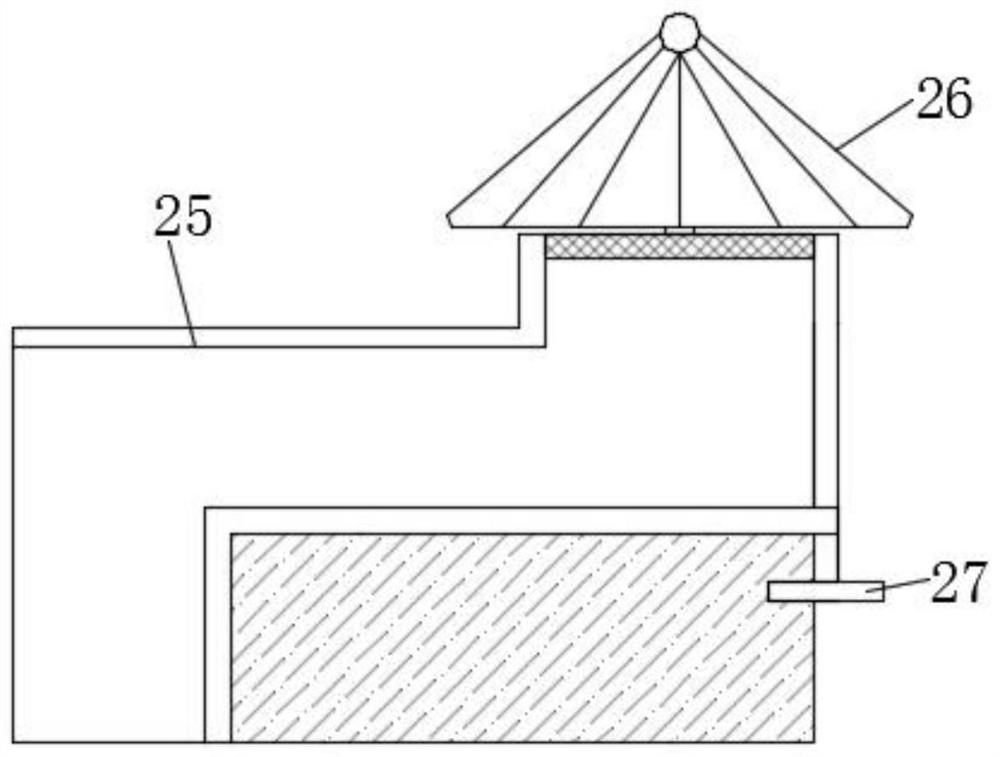
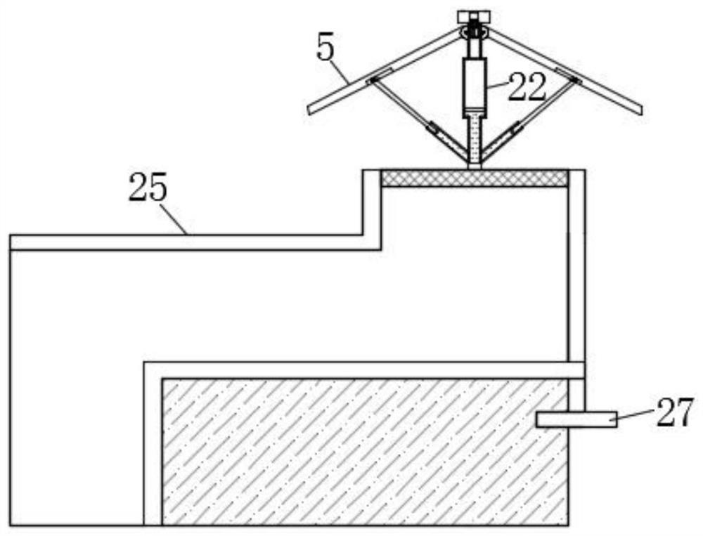
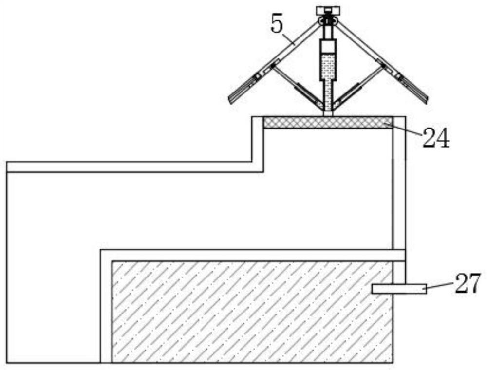
The invention discloses a building ventilation shaft structure with a rainproof function. The building ventilation shaft structure comprises a shaftway, a guide pipe is arranged at the opening position of the upper end face of the shaftway, and a supporting rod is vertically and fixedly installed on the upper end face of the guide pipe. According to the building ventilation shaft structure, rainwater falls into a water collecting groove in the upper end face of a T-shaped heat conduction metal block and enters a first sliding cavity along a through hole, a first water absorption expansion ball pushes first pistons to move upwards after absorbing water, the two first pistons push a second piston to move upwards, the second piston drives the second piston to move upwards through a second guide rod, the second piston slides upwards along a negative pressure groove, negative pressure is formed on the lower portion of the second piston, then a fourth piston moves upwards, the liquid level of liquid below the fourth piston rises, liquid inside the guide pipe is pumped into a supporting rod, the lower end of a rotating bone is gradually close to the edge position of an opening in the upper end of the shaftway, the rainwater is prevented from entering the shaftway, the safe use of a fan is ensured, and the use cost is reduced.

Description

technical field [0001] The invention relates to the technical field of air shafts, in particular to a building ventilation shaft structure with a rainproof function. Background technique [0002] The air shaft is usually poured with cement above the open section of the entrance and exit, and several exhaust and air intake shaft rooms above the floor level are poured on the ground. The air from the underground building rises into the exhaust shaft chamber through the roof of the underground building. The entrances and exits of the air shaft are mostly located in places with green vegetation. The peripheral side walls of the well chamber perpendicular to the ground are provided with louvers for ventilation. The exhaust fan passes through the louvers The air is exhausted to the outside. In order to prevent ground water from seeping into the air shaft from the louvers, the louvers are at a certain height from the ground, making the structure of the entire well chamber relatively...

Claims


Application Information

Patent Timeline
IPC IPC(8): E04F17/04E04F10/02
CPCE04F17/04E04F10/02
Inventor 王飞孙瑞琨褚洪官陈德超严保山
Owner 江苏天宇设计研究院有限公司
Learn More