Three-phase imbalance adjusting device and method based on phase-change switch

A technology of commutation switch and balance adjustment, which is applied in the direction of reducing the asymmetry of the multi-phase network and eliminating/reducing the asymmetry of the multi-phase network. Achieve the effects of convenient unified management, extended service life and wide application range

Pending Publication Date: 2021-12-17
HANGZHOU YUNUO ELECTRONICS TECH
View PDF1 Cites 0 Cited by
  • Summary
  • Abstract
  • Description
  • Claims
  • Application Information

AI Technical Summary

Problems solved by technology

[0005] 1 Causes the loss of distribution transformers and lines to increase, reducing the reliability of power supply;
[0006] 2 The distribution transformer will generate a large zero-sequence current when the three-phase load is seriously unbalanced, and the zero-sequence flux generated by the zero-sequence current will cause the transformer to generate additional iron loss and generate heat. In severe cases, the distribution transformer will be burned
Generate zero-sequence current through the neutral wire, causing additional loss, and in severe cases, the neutral wire will be burned;
[0007] 3 The quality of the heavy-duty phase power supply voltage is greatly reduced;
[0008] 4. It causes the neutral point of the system to shift, and the voltage at the end of the heavy-duty phase is low, resulting in partial load failure, resulting in a reduction in the output of the distribution transformer and a decrease in power conversion efficiency;
However, there are still some defects in the above-mentioned scheme. For example, the above-mentioned scheme cannot fundamentally solve the problem of actual load balance distribution. It is not suitable to install the adjustment device of the above-mentioned scheme in the distribution station area where the conventional low-voltage reactive power compensation device has been configured, resulting in the above-mentioned adjustment device. The scope of application is limited

Method used


Image

  • Three-phase imbalance adjusting device and method based on phase-change switch
  • Three-phase imbalance adjusting device and method based on phase-change switch
  • Three-phase imbalance adjusting device and method based on phase-change switch

Examples


Embodiment 1

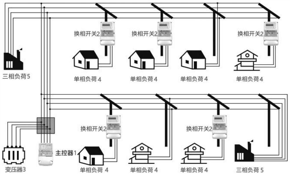
[0077] This embodiment provides a three-phase unbalance adjustment device based on commutation switches, including a main controller 1 and several commutation switches 2 . Such as figure 1 As shown, the main controller 1 is installed at the outgoing line end of the transformer 3, and the phase change switch 2 is installed at the incoming line end of the corresponding single-phase load 4. When put into use, all the incoming lines of the single-phase load 4 can be A phase-changing switch 2 is installed at each terminal, and a phase-changing switch 2 can also be selectively installed at the incoming line terminals of several single-phase loads 4, which can be installed by technicians as required. The phase change switch 2 is not installed at the incoming line end of the three-phase load 5 . Each reversing switch 2 is communicatively connected to the main controller 1 corresponding to the station area. The main controller of this embodiment adopts the main controller of Yunuo Co...

Embodiment 2

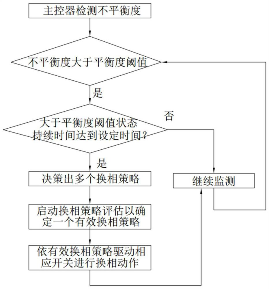
[0080] Such as figure 2 As shown, this embodiment provides a three-phase unbalance adjustment method based on a commutation switch, including the following steps:

[0081] S1. The main controller 1 obtains the electric energy parameters including the degree of unbalance, and compares the current degree of unbalance with the threshold value of the degree of balance;

[0082] S2. When the current unbalance degree continuously exceeds the balance degree threshold within the set time period, that is, when the duration of the state where the unbalance degree is greater than the balance degree threshold reaches the set time, the main controller 1 traverses each commutation switch 2, Obtain switch data such as the current phase, current, historical number of actions, and whether there is a self-test fault of each phase-changing switch 2, and then obtain the switching data, sampling and / or calculation of each phase-changing switch 2, including unbalance, three-phase Voltage, three-p...

Embodiment 3

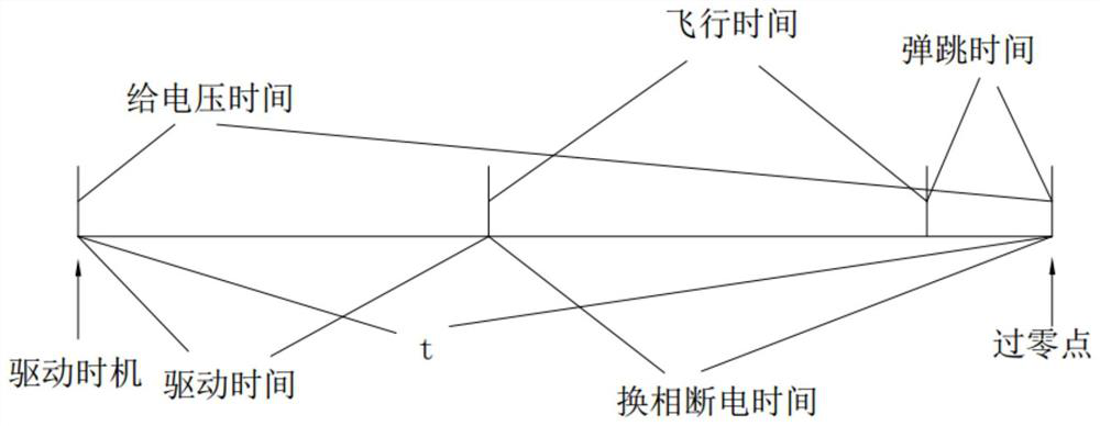
[0172] This embodiment is similar to Embodiment 2, the difference is that in Embodiment 1 and Embodiment 2, there is no restriction on the driving timing and voltage supply time of the commutation switch 2. Based on Embodiment 1 and Embodiment 2, those skilled in the art The driving timing and voltage supply time can be determined according to the power-off time and driving time in each parameter of the selected reversing switch to meet the zero-crossing switching.

[0173]However, with the aging of the actuator of the commutation switch 2, the change of the driving force of the driving power and many other factors, the contact driving time and commutation power-off time (flight time + bounce time) have a certain degree of discreteness. From a long-term perspective, the contact The drive time, flight time, and bounce time of the dots get progressively longer. If a certain voltage supply time and driving timing are used throughout the life cycle of the commutation switch, it wi...


PUM


Abstract

The invention provides a three-phase imbalance adjusting device and method based on phase-change switches. The three-phase imbalance adjusting device comprises a main controller and a plurality of phase-change switches, wherein the main controller is installed at the wire outlet end of a transformer, the phase-change switches are installed at the wire inlet ends of corresponding single-phase loads, and the main controller is in communication connection with the phase-change switches. According to the scheme, the problem of actual load distribution is fundamentally solved, the line loss rate of the transformer area is reduced while the problem of three-phase load imbalance is treated, and the concept of treating both symptoms and root causes is met.

Description

technical field [0001] The invention belongs to the technical field of DC resistance test of offshore transformer windings, and in particular relates to a three-phase unbalance adjustment device and an adjustment method based on a commutation switch. Background technique [0002] Three-phase current imbalance is an important index to measure the quality of power grid, and the quality of power grid directly determines the quality of power consumption of users, and its importance is self-evident. [0003] The power load of the low-voltage distribution network is relatively complex, and most of them are single loads. Although the load has been evenly distributed to the three phases A, B, and C during the construction of the station area, due to the randomness of users' electricity consumption habits and loads, the actual The upper load cannot achieve balanced distribution, which is the root cause of the unbalanced three-phase load problem. [0004] The harm caused by the unbal...

Claims


Application Information

Patent Timeline
IPC IPC(8): H02J3/26
CPCH02J3/26Y02E40/50
Inventor 徐保华韩德昆朱旭余
Owner HANGZHOU YUNUO ELECTRONICS TECH
Why Eureka
Try Eureka