Rear wall outer plate clamp

A technology of enclosure panels and fixtures, which is applied in the field of automotive sheet metal parts, can solve problems such as easy deviation, difficult fixation, and large volume, and achieve the effects of reducing impact and wear, improving product quality, and ensuring accuracy

Pending Publication Date: 2021-12-14
安徽泓毅汽车技术股份有限公司
View PDF1 Cites 0 Cited by
  • Summary
  • Abstract
  • Description
  • Claims
  • Application Information

AI Technical Summary

Problems solved by technology

[0002] At present, due to the development of the national economy, the improvement of living standards and the rapid development of automobile sales, automobiles have entered thousands of households. After being fixed, welding is carried out. During the processing of the outer plate of the rear wall and rear beam, due to its large volume and unevenness, it is not easy to fix and easily shift during processing operations, which affects the efficiency of processing operations. Patent No. CN207807161U discloses a rear wall The rear beam outer panel clamp is used to fix the rear wall outer panel as a whole by setting multiple pressure columns, setting the supporting surface for support, and setting multiple limit columns to limit the position, so as to complete the effective fixing of the rear wall outer panel of the car. However, the fixture is aimed at the overall fixing of the rear wall outer panel, and lacks effective fixing and positioning for the welded parts of the rear wall outer panel. During welding, the welded parts are easy to shift and affect the welding quality. Therefore, it is very important to solve this problem.

Method used


Image

  • Rear wall outer plate clamp
  • Rear wall outer plate clamp
  • Rear wall outer plate clamp

Examples


Embodiment Construction

[0019] In order to deepen the understanding of the present invention, the present invention will be further described below in conjunction with examples, which are only used to explain the present invention and do not constitute a limitation to the protection scope of the present invention.

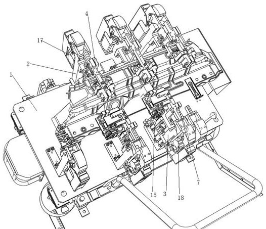
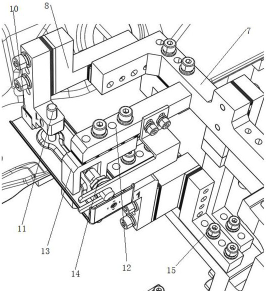
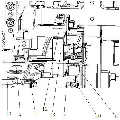
[0020] Such as Figure 1-4 As shown, the present embodiment provides a rear wall outer panel clamp, including a bottom plate 1, a front bracket 2 is provided on the front side of the bottom plate 1, a placement frame 3 is provided on the rear side of the front bracket 2, and the rear wall outer panel is positioned on the placement frame 3 On, the upper end of the front bracket 2 is rotatably connected with the front clamp arm 4, the front bracket 2 is provided with a drive cylinder 17, the output end of the drive cylinder 17 is connected with the front end of the front clamp arm 4, and the drive cylinder 17 works to drive the front clamp arm 4 to rotate, and the front clamp The upper and ...


PUM


Abstract

The invention provides a rear wall outer plate clamp. The clamp comprises a bottom plate, a front support is arranged on the front side of the bottom plate, a containing frame is arranged on the rear side of the front support, a front clamping arm is rotatably connected to the upper end of the front support, a front pressing block is installed at the rear end of the front clamping arm, a rear support is arranged on the rear side of the bottom plate, a rear clamping arm is rotatably arranged on the rear support, and a fixing frame is installed at the front end of the rear clamping arm. A rear pressing block is arranged on the front side of the left end of the fixing frame, an upper positioning pin is inserted on the rear side of the left end of the fixing frame, a connecting frame is arranged on the left side edge of the middle of the rear clamping arm, an n-shaped positioning block is arranged on the lower side of the connecting frame, a sensor is installed on the portion, corresponding to the middle of the positioning block, of the rear side of the connecting frame, a supporting frame is arranged on the front side of the rear support, and a lower positioning pin is arranged at the front end of the supporting frame. A welding part is pressed and fixed through the rear pressing block, the two ends of the welding part are located from the upper side and the lower side through the upper positioning pin and the lower positioning pin respectively, the welding part is pressed and located through the positioning block, the hole position of the welding part is inducted through the sensor, the placing accuracy of the position of the welding part is effectively guaranteed, the structure is simple, and use is convenient and fast.

Description

technical field [0001] The invention relates to the technical field of automobile sheet metal parts, in particular to a rear wall outer panel clamp. Background technique [0002] At present, due to the development of the national economy, the improvement of living standards and the rapid development of automobile sales, automobiles have entered thousands of households. After being fixed, welding is carried out. During the processing of the outer plate of the rear wall and rear beam, due to its large volume and unevenness, it is not easy to fix and easily shift during processing operations, which affects the efficiency of processing operations. Patent No. CN207807161U discloses a rear wall The rear beam outer panel clamp is used to fix the rear wall outer panel as a whole by setting multiple pressure columns, setting the supporting surface for support, and setting multiple limit columns to limit the position, so as to complete the effective fixing of the rear wall outer panel...

Claims


Application Information

Patent Timeline
Patent Type & Authority Applications(China)
IPC IPC(8): B23K37/04
CPCB23K37/04B23K37/0443
Inventor 陈启立张俊夏康王健
Owner 安徽泓毅汽车技术股份有限公司
Why Eureka
Try Eureka