Electric connector

A technology of electrical connectors and connecting arms, which is applied in the direction of connections, circuits, and parts of connection devices, etc., which can solve problems such as breaking, destroying the structure of conductive terminals, and unfavorable deformation of the upper elastic arm.

Active Publication Date: 2021-12-10
DEYI PRECISION ELECTRONIC IND CO LTD PANYU
View PDF5 Cites 0 Cited by
  • Summary
  • Abstract
  • Description
  • Claims
  • Application Information

AI Technical Summary

Problems solved by technology

[0003] When the contact part is docked with a chip module, the upper elastic arm is deformed under force, so the bent part is subjected to a relatively large stress, but the connecting material part extends upward from the bent part to strengthen The structural strength of the bending part is improved, but the bending part is not easy to be elastically deformed, which is not conducive to the force deformation of the upper spring arm, and when the material tape is broken, the bending part is subjected to pressure in the left and right directions. breaking force, it is easy to destroy the performance of the bending part
[0004] In addition, the conductive terminal connected to the material tape is assembled to the insulating body, and there is a gap between the conductive terminal and the groove wall of the terminal groove in the left-right direction, and when it is swung in the left-right direction perpendicular to the front-rear direction, the In the process of breaking the connection between the material belt and the material belt, when the material belt is forced to drive the material belt to deflect to one side in the left and right direction, the upper elastic arm The position connecting the material connection part will also be deflected to one side under force. However, when the breaking force applied by the operator is too large, the deflection angle of the elastic arm in the lateral direction will be too large, and it is easy to make the upper spring The arm is deformed to destroy the structure of the conductive terminal, or even break or break the conductive terminal

Method used


Image

  • Electric connector
  • Electric connector
  • Electric connector

Examples


Embodiment Construction

[0036] In order to facilitate a better understanding of the purpose, structure, features, and effects of the present invention, the present invention will now be further described in conjunction with the accompanying drawings and specific embodiments.

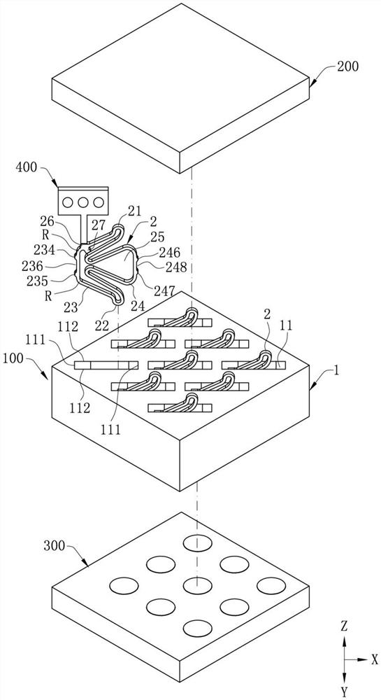
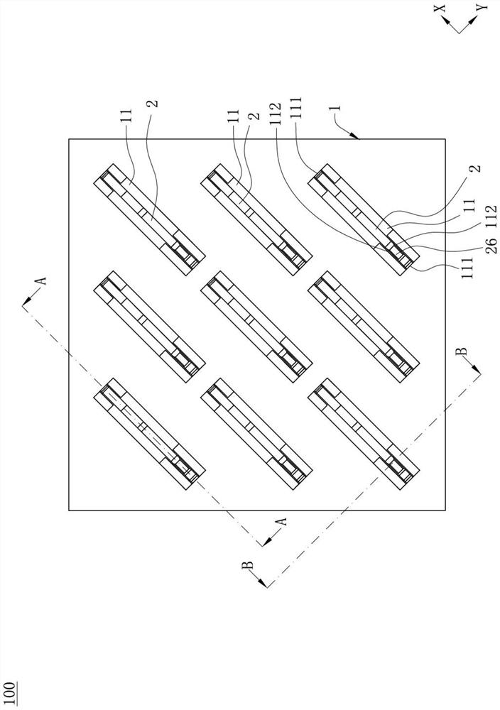
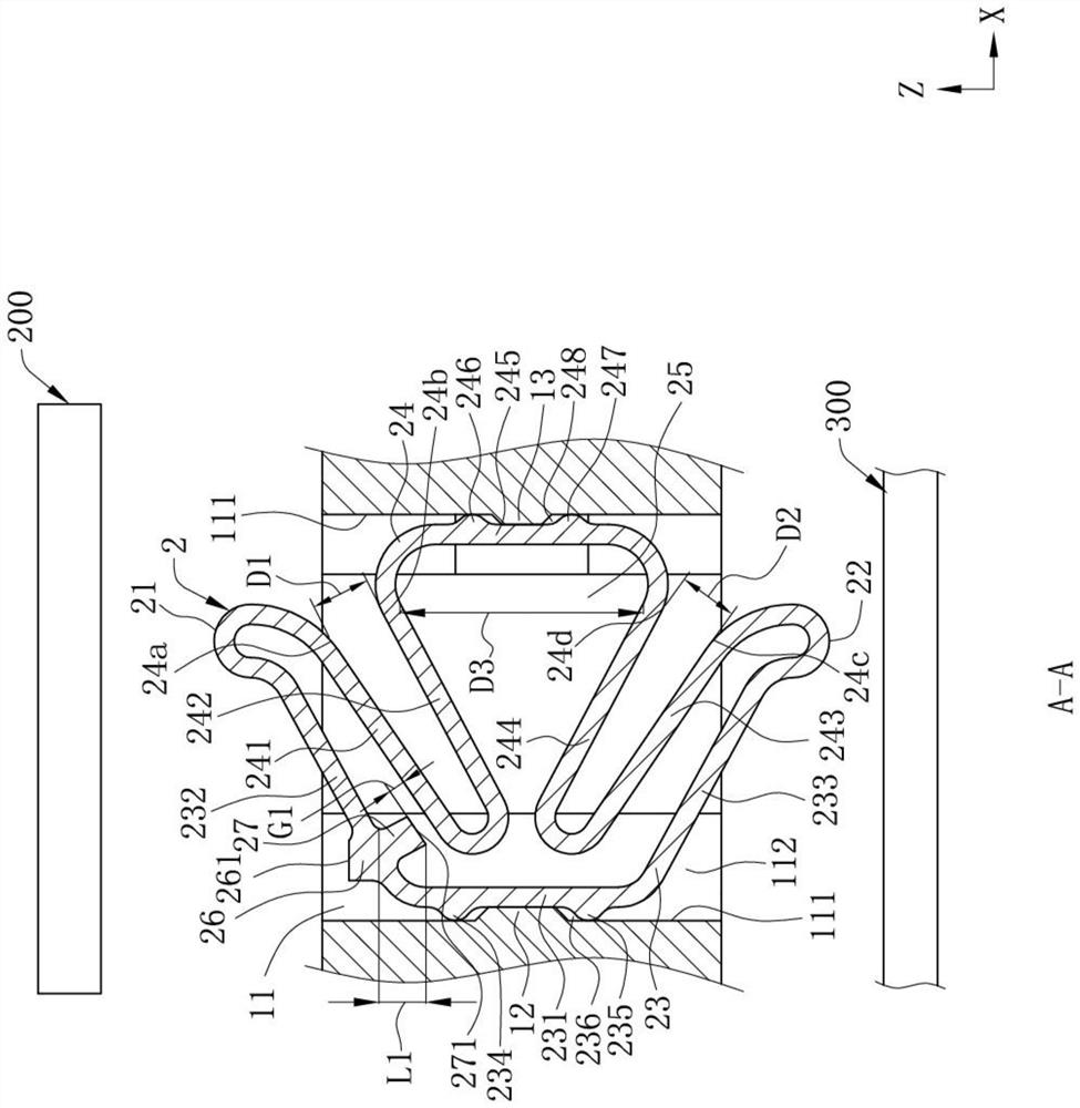
[0037] For the convenience of describing the specific structure of an electrical connector 100 of the present invention, a front-rear direction, a left-right direction, and an up-down direction are defined, and the front-rear direction, the left-right direction, and the up-down direction are perpendicular to each other, so The forward direction in the front and rear directions is the positive direction of the X axis, the rightward direction in the left and right directions is the positive direction of the Y axis, and the upward direction in the up and down directions is the positive direction of the Z axis.

[0038] Such as figure 1 As shown, in the up-and-down direction, the electrical connector 100 is used to electrically conne...


PUM


Abstract

The invention discloses an electric connector. The electric connector comprises: an insulating body which is provided with a terminal groove penetrating up and down; and a conductive terminal accommodated in the terminal groove. The conductive terminal comprises: a contact part; a guide connection part; an extension arm and a connecting arm which are connected with the contact part and the guide connection part, wherein the connecting arm is located in front of the extension arm, the sides, facing each other, of the extension arm and the connecting arm are arranged as inner sides, the sides, deviating from each other, of the extension arm and the connecting arm are arranged as outer sides, the extension arm comprises a base part, an upper elastic arm for connecting the base part and the contact part, and a lower elastic arm for connecting the base part and the guide connection part, and a bent part is formed at the joint of the upper elastic arm and the base part; a material connecting part formed by extending outwards from the outer side of the upper elastic arm, wherein the material connecting part is far away from the base part compared with the bent part; and a limiting part formed by extending inwards from the inner side of the upper elastic arm, wherein the limiting part and the material connecting part are oppositely arranged relative to the upper elastic arm, the limiting part is located in the terminal groove, and when the material connecting part is stressed to deflect towards one side in the left-right direction, the limiting part deflects towards the opposite side in the left-right direction and is limited by the groove wall of the terminal groove.

Description

【Technical field】 [0001] The invention relates to an electrical connector, in particular to an electrical connector capable of simultaneously transmitting electrical signals through two paths. 【Background technique】 [0002] Existing electrical connectors generally include an insulating body and a plurality of conductive terminals, and the plurality of conductive terminals are arranged in a plurality of terminal grooves of the insulating body, and each conductive terminal includes a base, an upper elastic arm, and a lower elastic arm and a connecting arm, the base extends up and down and is arranged in the terminal slot, the upper elastic arm extends upward and forward from the base, and the upper elastic arm protrudes upward to form a contact portion for In order to be in electrical contact with a first docking member, the lower elastic arm is formed by extending downward and forward from the base, and the lower elastic arm protrudes downward to form a guiding portion for c...

Claims


Application Information

Patent Timeline
Patent Type & Authority Applications(China)
IPC IPC(8): H01R13/24
CPCH01R13/2414H01R13/245
Inventor 黄常伟
Owner DEYI PRECISION ELECTRONIC IND CO LTD PANYU
Why Eureka
Try Eureka