
A pressure relief arrangement

A technology for releasing device and pressure, applied in valve device, substation/distribution device casing, cooling/ventilation of substation/switchgear, etc., can solve the problem of increasing the explosive rupture of casing, release pressure in a fast and effective way, and pressure release path The area is not large enough, etc.

Pending Publication Date: 2021-12-10
ABB (SCHWEIZ) AG
View PDF0 Cites 0 Cited by
  • Summary
  • Abstract
  • Description
  • Claims
  • Application Information

AI Technical Summary

Problems solved by technology

[0003] One problem with prior art pressure relief devices is that the area of ​​the pressure relief path for the hot gas may not be large enough
A pressure relief hatch providing a small area in the pressure relief path cannot relieve the pressure in a quick and efficient manner, thereby increasing the risk of explosive rupture of the enclosure

Method used


Image

  • A pressure relief arrangement
  • A pressure relief arrangement
  • A pressure relief arrangement

Examples


Embodiment Construction

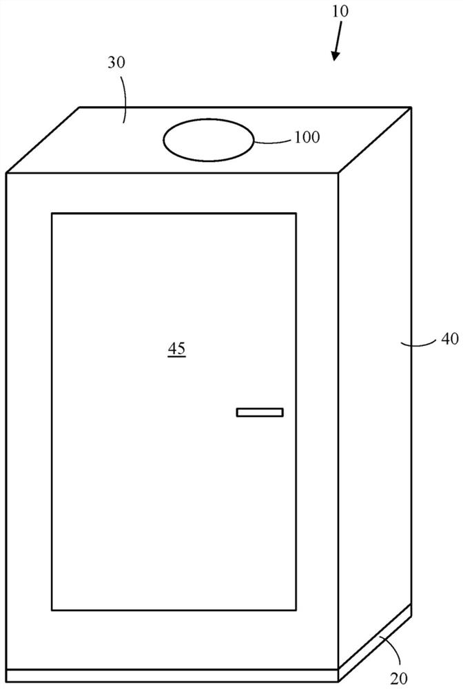
[0028] figure 1 Shown is an electrical cabinet with a pressure relief device.

[0029] The electrical cabinet 10 includes a bottom 20 , a top 30 and a side wall 40 extending between the bottom 20 and the top 30 of the electrical cabinet 10 . The front wall of the electrical cabinet 10 may include a door 45 . A pressure relief device based on a pressure relief hatch 100 may be positioned on the top 30 of the electrical cabinet 10 . However, the pressure relief hatch 100 may be positioned on any wall 40 of the electrical cabinet 10 . Wall 40 may be an exterior side wall of electrical cabinet 10 or be on an interior side wall of electrical cabinet 10 . The electrical cabinet 10 may include electrical equipment such as bus bars, electrical drives for electric motors, and the like.

[0030] The pressure relief hatch 100 may be positioned to connect with openings in the walls 30 , 40 of the electrical cabinet 10 .

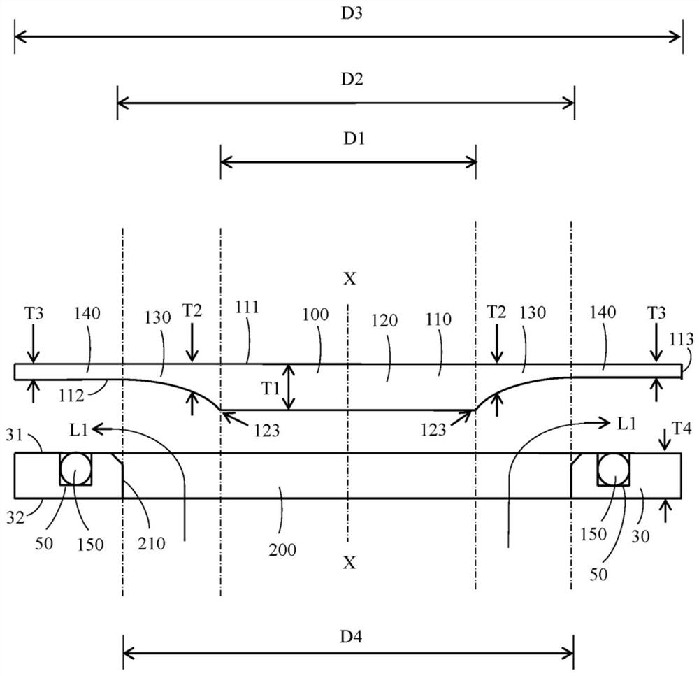
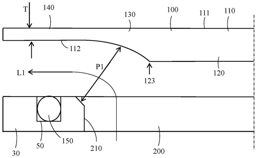
[0031] figure 2 A pressure relief device according to the in...


PUM


Abstract

The invention relates to a pressure relief arrangement. The arrangement comprises a pressure relief hatch (100) for closing an opening (200) in a wall (30) in an electric cabinet. The pressure relief hatch comprises a body (110) having an outer surface (111), an opposite inner surface (112), an outer perimeter (113), and a thickness. The body comprises a center portion (120) with a first thickness (T1), an intermediate portion (130) with a second thickness (T2), and an outer portion (140) with a third thickness (T3). The first thickness is greater than the third thickness and the second thickness decreases in a radially outward direction from the first thickness to the third thickness. A spring keeps the pressure relief hatch in a closed position in the opening during normal operation of the electric cabinet.

Description

technical field [0001] The present invention relates to pressure relief devices. Background technique [0002] The pressure relief means may be formed by a pressure relief hatch mounted on the housing comprising the electrical equipment. A short circuit within the enclosure may ignite an arc within the enclosure. An electric arc can heat the air around the arc, causing the air to expand explosively. The pressure inside the enclosure will thus increase, causing deformation of the enclosure. Deformation may rupture the enclosure, creating a hazard to persons outside the enclosure. Therefore, a pressure relief hatch or other similar device is added to the closed enclosure in order to vent the pressure caused by the arc. Thus, the pressure will be released in a controlled manner and in a controlled direction through the pressure release hatch in the housing. [0003] One problem with prior art pressure relief devices is that the area of ​​the pressure relief path for the ho...

Claims


Application Information

Patent Timeline
IPC IPC(8): F16K17/04F16K17/164H02B1/56H02B1/30
CPCF16K17/0413F16K17/164H02B1/565H02B1/30H02B1/28H02B1/013H02B1/306H05K5/068
Inventor 佩里·哈尔蒂凯宁泰穆·萨尔米亚汉娜·拉皮诺亚
Owner ABB (SCHWEIZ) AG
Learn More