
Enhanced hydraulic retarder for commercial vehicle

A technology of enhancing fluid and retarder, which is applied in the direction of fluid transmission, belt/chain/gear, mechanical equipment, etc., and can solve the problem of not fully satisfying the normal use of commercial vehicles, long exit time of high temperature protection, and affecting downhill retardation, etc. problem, to achieve the effect of large reaction torque, long service life, and meet braking requirements

Active Publication Date: 2021-12-10
山东泰鑫汽车科技有限公司
View PDF6 Cites 0 Cited by
  • Summary
  • Abstract
  • Description
  • Claims
  • Application Information

AI Technical Summary

Problems solved by technology

[0003] At present, the hydraulic retarders that have been listed and publicly reported in China have the following common shortcomings: 1. They cannot fully meet the normal use of commercial vehicles with a load of more than 50 tons.
2. It cannot meet the normal driving requirements of freight commercial vehicles on slopes with a speed exceeding 80Km / H and a downhill steepness exceeding 6%.
3. The fuel consumption of a commercial vehicle equipped with a hydraulic retarder increases by nearly 2% to 5%.
4. The heat exchange is slow. When the temperature is too high, the high temperature protection exit time is too long, which affects the downhill slowing speed

Method used


Image

  • Enhanced hydraulic retarder for commercial vehicle
  • Enhanced hydraulic retarder for commercial vehicle
  • Enhanced hydraulic retarder for commercial vehicle

Examples


Embodiment Construction

[0041] The present invention will be further described below in conjunction with the accompanying drawings and specific embodiments. The technical solutions in the embodiments of the present invention are clearly and completely described, and the described embodiments are only part of the embodiments of the present invention, not all of them. Based on the embodiments of the present invention, all other embodiments obtained by persons of ordinary skill in the art without making creative efforts belong to the protection scope of the present invention.

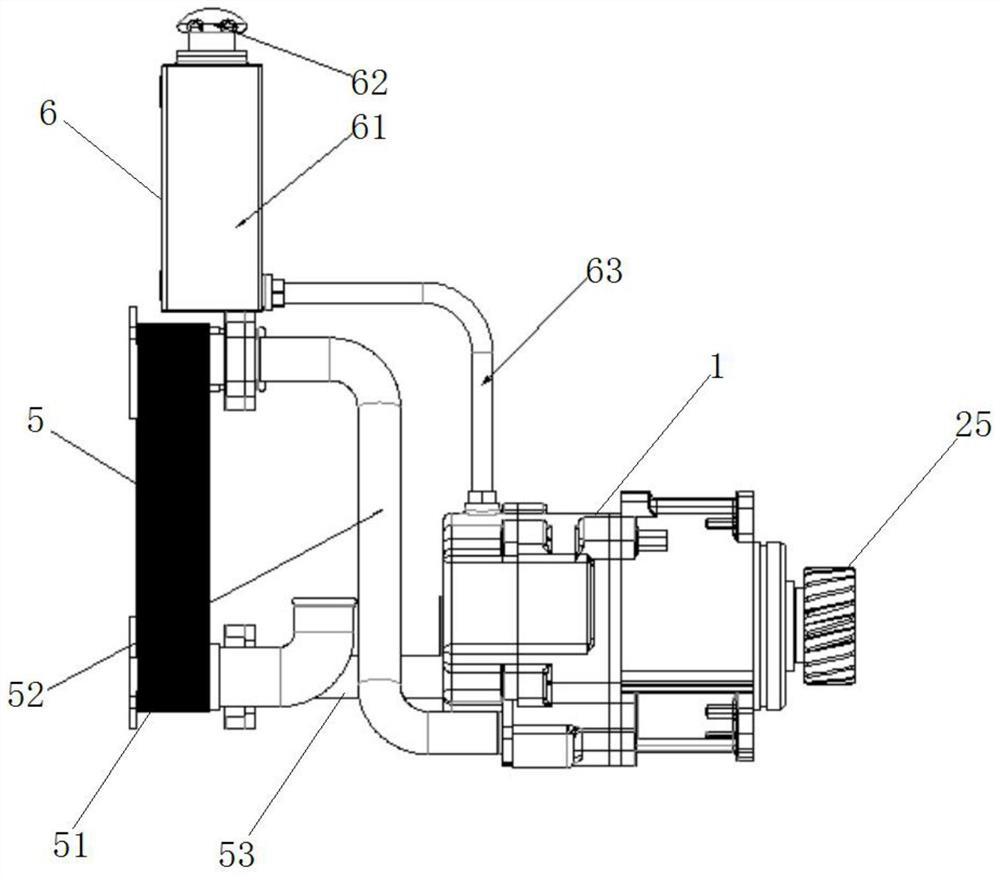
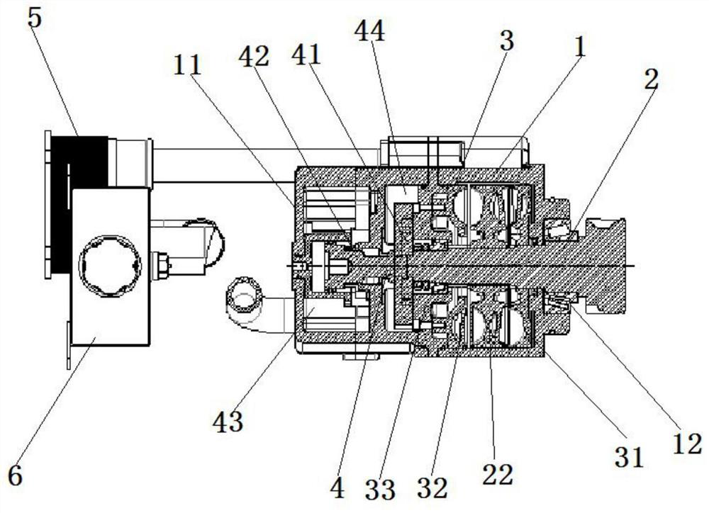
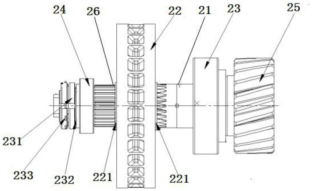
[0042] Such as figure 1 , 2 , 11, the patent of the present invention designs an embodiment of a commercial vehicle enhanced hydraulic retarder. In this embodiment, the commercial vehicle enhanced hydraulic retarder includes a casing 1, a power transmission mechanism 2, Anti-braking force generating mechanism 3, oil supply mechanism 4, heat exchange mechanism 5 and auxiliary oil tank 6.

[0043] to combine image 3 As shown, ...


PUM


Abstract

The invention relates to an enhanced hydraulic retarder for a commercial vehicle, and belongs to the technical field of vehicle accessories. The hydraulic retarder comprises a machine shell, a power transmission mechanism, a counter braking force generation mechanism, an oil supply mechanism and a heat exchange mechanism, wherein the power transmission mechanism comprises a gear spline main shaft, a middle turbine, a main bearing and an auxiliary bearing, the middle turbine is connected to the middle of the gear spline main shaft in a matched mode through a spline, the middle turbine is a double-face turbine; the counter braking force generating mechanism comprises a front fixed turbine, a rear fixed turbine and a rear fixed turbine fixing seat, a turbine cavity is formed between the rear fixed turbine fixing seat and the front side face of the machine shell, the gear spline main shaft transversely penetrates into the machine shell from the center of the front side face of the machine shell, and the middle turbine is located between the front fixed turbine and the rear fixed turbine. Counter braking force of the hydraulic retarder is generated by the middle turbine, the front fixed turbine and the rear fixed turbine together, so that the retarding effect is better, and control is more accurate.

Description

technical field [0001] The invention relates to the technical field of vehicle accessories, in particular to an enhanced hydraulic retarder for commercial vehicles. Background technique [0002] In the use of hydraulic retarder, the automobile retarder reduces the speed of the vehicle downhill through the hydraulic device. Large commercial trucks use the exhaust brake for a long time when going down the long slope, which makes the truck hub heat up and the truck braking effect becomes poor. In severe cases, the braking force will be lost, which will affect driving safety. The hydraulic retarder can play a very good auxiliary role in the long-distance braking of commercial trucks. Existing hydraulic retarders currently on the market generally consist of a stator, a rotor, an oil pump, an oil storage tank and a heat exchanger. The stator is also the housing of the retarder, which is connected to the rear end of the transmission or the vehicle frame. The rotor is connected to...

Claims


Application Information

Patent Timeline
Patent Type & Authority Applications(China)
IPC IPC(8): F16H41/04F16H41/24
CPCF16H41/04F16H41/24F16H2041/285Y02T10/64
Inventor 沈燕红
Owner 山东泰鑫汽车科技有限公司
Learn More