Detection device for preventing dislocation of vacuum pump rotor of vacuum sputtering instrument
A vacuum sputtering and detection device technology, which is applied to components, pumps, and pump control of elastic fluid pumping devices. It can solve problems such as rotor misalignment, low production efficiency, and overheating of the pump body to improve production efficiency. and stability, improving equipment safety, improving equipment maintenance efficiency and production efficiency
- Summary
- Abstract
- Description
- Claims
- Application Information
AI Technical Summary
Problems solved by technology
Method used
Image
Examples
Embodiment 1
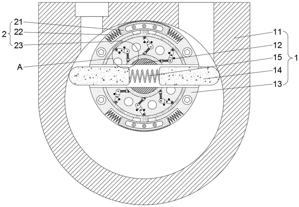
[0026] see figure 1 , a detection device for vacuum sputtering instrument to prevent vacuum pump rotor misalignment, comprising a pumping mechanism 1, a detection mechanism 2 is movably connected inside the pumping mechanism 1, the detection mechanism 2 includes a slider 21, and the pumping mechanism 1 is provided with a The slot compatible with the slide block 21 is used to install the slide block 21 to facilitate the movement of the slide block 21. Both sides of the slide block 21 are movable with return springs 22 for driving the slide block 21 to reset. The inside of the slide block 21 is fixedly connected with Swivel 23.
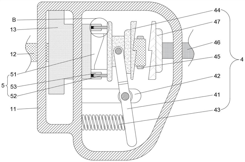
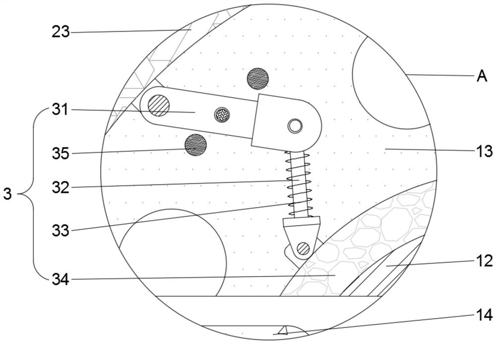
[0027] After the rotor 13 is dislocated, the detection mechanism 2 and the transmission mechanism 3 are triggered during operation to realize the function of automatically detecting the position of the rotor 13, improving equipment stability and production efficiency; the clutch mechanism 4 is triggered during the operation of the transmission mechanism...
Embodiment 2
[0032] see Figure 1-4 , a detection device for a vacuum sputtering instrument to prevent vacuum pump rotor misalignment, including an air pumping mechanism 1, the air pumping mechanism 1 includes a housing 11, and the top of the housing 11 is provided with an air inlet and an exhaust port for vacuuming , the middle part of the housing 11 is movably connected with the driven shaft 12, the outer ring of the driven shaft 12 is fixedly connected with the rotor 13, the middle part of the rotor 13 is movably connected with the rotating rod 14, and the middle part of the rotating rod 14 is movably connected with a push-pull spring 15, and the inside of the rotor 13 is set There is a groove suitable for the rotating rod 14 and the push-pull spring 15, which is used to install the rotating rod 14, so as to facilitate the movement of the rotating rod 14, and the detection mechanism 2 is movably connected inside the air extraction mechanism 1, and the detection mechanism 2 includes a sli...
PUM
 Abstract
Description
Claims
Application Information
 - R&D Engineer
- R&D Manager
- IP Professional
- Industry Leading Data Capabilities
- Powerful AI technology
- Patent DNA Extraction
Browse by: Latest US Patents, China's latest patents, Technical Efficacy Thesaurus, Application Domain, Technology Topic, Popular Technical Reports.
© 2024 PatSnap. All rights reserved.Legal|Privacy policy|Modern Slavery Act Transparency Statement|Sitemap|About US| Contact US: help@patsnap.com


