
Cutter device

A technology of cutter and cutter assembly, applied in metal processing and other directions, can solve problems such as low production efficiency, and achieve the effect of improving production efficiency and reducing the time required

Pending Publication Date: 2021-12-07
SHENZHEN CHENGJIE INTELLIGENT EQUIP CO LTD
View PDF4 Cites 0 Cited by
  • Summary
  • Abstract
  • Description
  • Claims
  • Application Information

AI Technical Summary

Problems solved by technology

[0003] The technical problem to be solved by the present invention is: aiming at the problem of low production efficiency of the existing cutter device, to provide a cutter device

Method used


Image

  • Cutter device
  • Cutter device
  • Cutter device

Examples


Embodiment Construction

[0024] In order to make the technical problems, technical solutions and beneficial effects solved by the present invention clearer, the present invention will be further described in detail below in conjunction with the accompanying drawings and embodiments. It should be understood that the specific embodiments described here are only used to explain the present invention, not to limit the present invention.

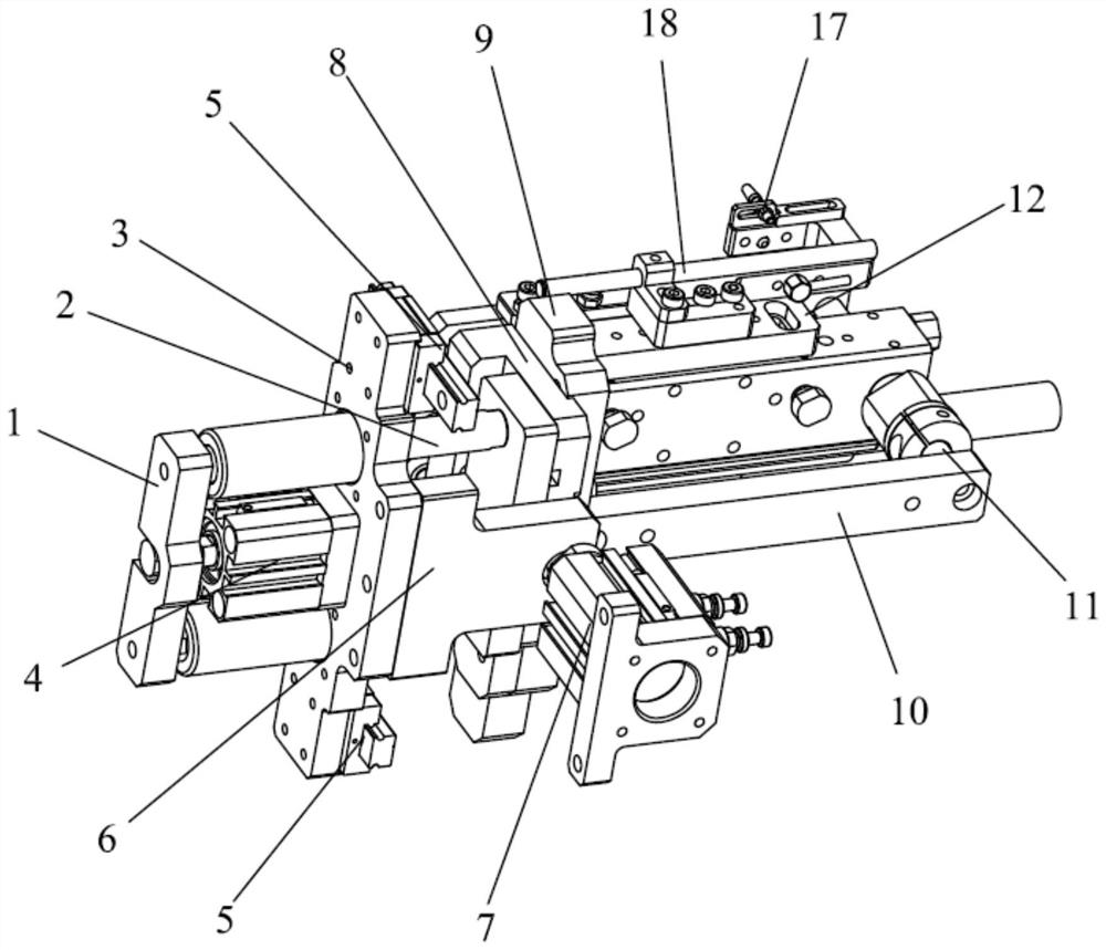
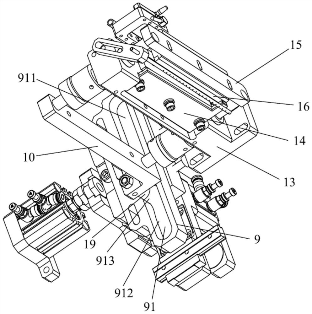
[0025] see figure 1 and figure 2 , the cutter device of the embodiment of the present invention includes a transfer assembly and 4 .

[0026] The transfer assembly includes a transfer mechanism and a cutter cam 9, the cutter cam 9 is provided with a guide groove 91, and the guide groove 91 includes an upper straight groove 911, a lower straight groove 912 and a straight groove connected to the upper straight groove 911. The arc groove 913 between the lower straight groove 912.

[0027] Described cutter assembly comprises push rod connecting plate 10, push rod 11, fix...


PUM


Abstract

The invention relates to a cutter device which comprises a transferring assembly and a cutter assembly; the transferring assembly comprises a transferring mechanism and a cutter cam, a guide groove is formed in the cutter cam, and the guide groove comprises an upper linear groove, a lower linear groove and an arc-shaped groove connected between the upper linear groove and the lower linear groove; the cutter assembly comprises a push rod connecting plate, a push rod, a fixed cutter holder, a fixed cutter, a movable cutter holder, a movable cutter and a contact piece, the movable cutter holder is fixed to one end of the push rod, the push rod connecting plate is fixed to the other end of the push rod, and the contact piece is installed on the push rod connecting plate; and the transferring mechanism is used for driving the cutter cam to move, so that the contact piece can enter and exit from the guide groove. According to the cutter device, a material is cut off through movement of a feeding mechanism, the response time of an air cylinder is not needed, and the material is cut off while feeding is completed. And the time required for cutting off the material is greatly shortened, and the production efficiency is improved.

Description

technical field [0001] The invention belongs to the technical field of cutting equipment, and in particular relates to a cutter device. Background technique [0002] According to the development of the times, the application of lithium batteries is becoming more and more extensive, and there are more and more types of lithium batteries, and there are also various equipment for producing corresponding lithium batteries. After the lithium battery equipment is wound, the material needs to be cut off with a cutter device to complete the winding. The existing cutter device is driven by the cylinder to cut the material. In this way, each time the feeding mechanism has to wait for the response of the cylinder to cut the material, which wastes time and reduces the production efficiency. Contents of the invention [0003] The technical problem to be solved by the present invention is to provide a cutter device for the problem of low production efficiency of the existing cutter dev...

Claims


Application Information

Patent Timeline
IPC IPC(8): B26D1/08B26D5/38
CPCB26D1/08B26D1/0006B26D5/38
Inventor 吴泽喜胡永超呙德红
Owner SHENZHEN CHENGJIE INTELLIGENT EQUIP CO LTD
Learn More