
Stator assembly and motor

A component and stator technology, applied in the shape/style/structure of electromechanical devices, electrical components, winding conductors, etc., can solve problems such as difficult production, high voltage difference, and motor failure, and reduce the risk of insulation breakdown. The effect of small voltage difference and improved power performance

Pending Publication Date: 2021-12-03
BYD CO LTD
View PDF3 Cites 0 Cited by
  • Summary
  • Abstract
  • Description
  • Claims
  • Application Information

AI Technical Summary

Problems solved by technology

[0002] In the field of motor technology, most of the windings used are in the form of welding both the upper and lower ends of the stator core. There are many solder joints and the process is complicated. In addition, after the flat wire is offline, it is difficult to fix it accurately and the production is difficult.
From the analysis of the electrical connection, the voltage difference between different layers of the winding in the same slot is high. When used under high voltage, the layers are easy to break down, resulting in a short circuit and causing the motor to fail.
The motor is full-pitch winding, and it is difficult to exert the maximum power performance of the motor under the limitation of voltage and current

Method used


Image

  • Stator assembly and motor
  • Stator assembly and motor
  • Stator assembly and motor

Examples


Embodiment Construction

[0059] Embodiments of the present invention are described in detail below, examples of which are shown in the drawings, wherein the same or similar reference numerals designate the same or similar elements or elements having the same or similar functions throughout. The embodiments described below by referring to the figures are exemplary only for explaining the present invention and should not be construed as limiting the present invention.

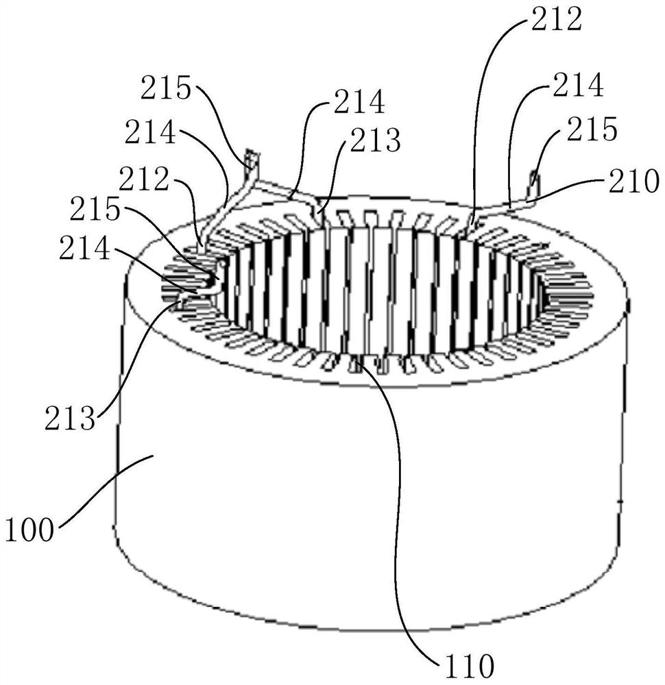
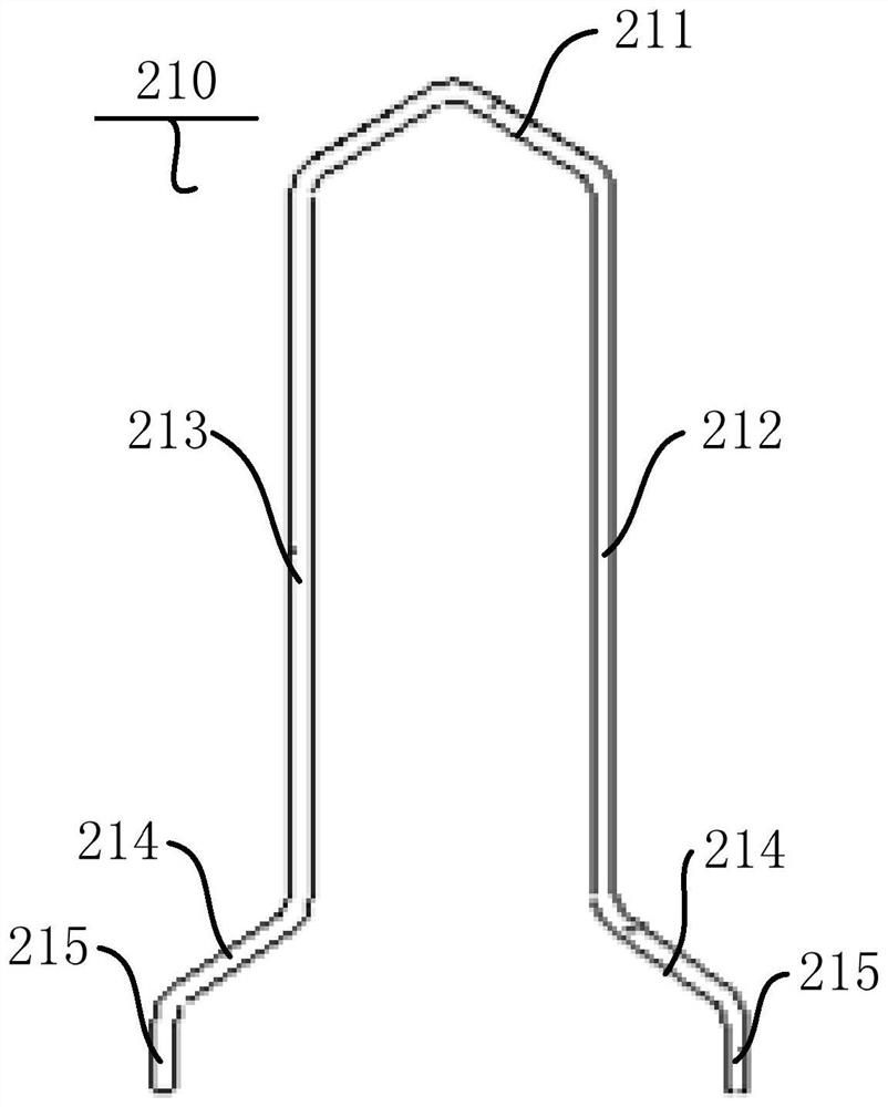
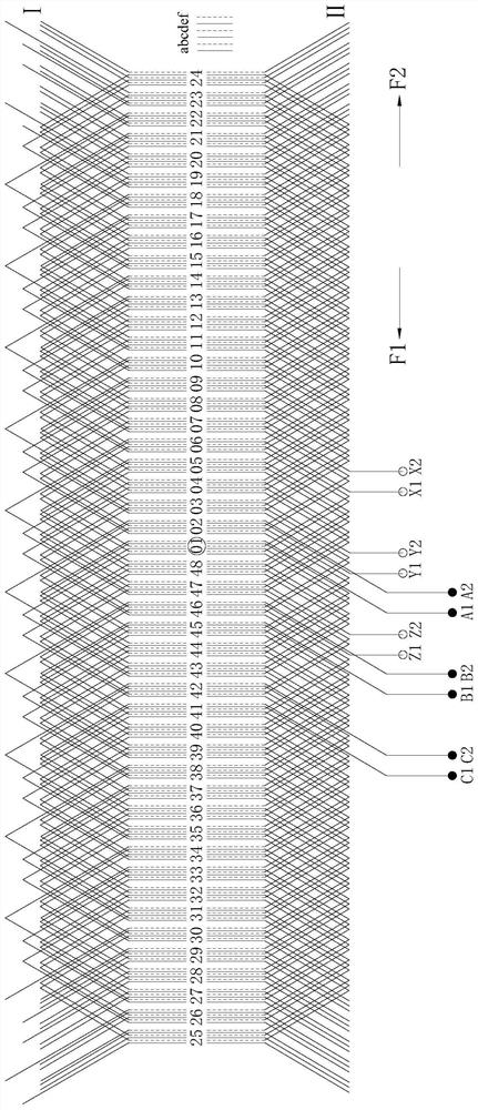
[0060] Refer below Figure 1-Figure 8 A stator assembly 1000 and an electric machine according to an embodiment of the present invention are described.

[0061] like Figure 1-Figure 8 As shown, the stator assembly 1000 according to the embodiment of the present invention is suitable for z-slot 2p class m-phase motors, the number of slots per pole and phase is q=z / m / (2p), and the number of parallel branches is a, a≤q. The number of slots z here can be 24, 48, 72, etc., the number of phases m can be three-phase, two-phase or single-pha...


PUM


Abstract

The invention discloses a stator assembly and a motor. The stator assembly is suitable for the motor with z slots, 2p poles and m phases, the slot number q of each pole and each phase of the motor is equal to z / m / (2p), the parallel branch number is a, a is smaller than or equal to q, and the stator assembly comprises a stator core, a first U-shaped conductor section, a second U-shaped conductor section, a third U-shaped conductor section and a fourth U-shaped conductor section. The span between a first in-groove part and a second in-groove part of the first U-shaped conductor section is y-1, and y is equal to z / (2p); the span between a first in-groove part and a second in-groove part of the second U-shaped conductor section is y-1; the span between a first in-groove part and a second in-groove part of the third U-shaped conductor section is y; and the span between a first in-groove part and a second in-groove part of the fourth U-shaped conductor section is y+1. According to the stator assembly, the number of welding spots is small, the U-shaped conductor sections are convenient to fix, the winding voltage difference between adjacent groove layers in the same groove is small, the insulation breakdown risk of a motor can be effectively reduced, and reliability is high.

Description

technical field [0001] The invention relates to the technical field of motors, in particular to a stator assembly and a motor. Background technique [0002] In the field of motor technology, most of the windings used are in the form of welding both the upper and lower ends of the stator core. There are many welding points and the process is complicated. In addition, after the flat wire is off the line, it is difficult to fix it accurately and the production is difficult. From the analysis of the electrical connection, the voltage difference between different layers of the winding is high in the same slot. When used under high voltage, the layers are easy to break down, resulting in a short circuit and causing the motor to fail. The motor is full-pitch winding, and it is difficult to exert the maximum power performance of the motor under the limitation of voltage and current. Contents of the invention [0003] The invention provides a stator assembly, which has the advanta...

Claims


Application Information

Patent Timeline
Patent Type & Authority Applications(China)
IPC IPC(8): H02K3/12H02K3/28
CPCH02K3/12H02K3/28H02K2213/03
Inventor 林焕炜
Owner BYD CO LTD
Learn More