
Photovoltaic energy storage cooperative operation control method

A photovoltaic energy storage and operation control technology, which is applied in photovoltaic power generation, energy storage, and single-grid parallel feeding arrangement, etc., can solve the problems of overloaded operation of transformers, increased safety risks of upper-level power grids, and high power consumption, so as to avoid reverse current and Effects of Transformer Overloading

Pending Publication Date: 2021-12-03
SHANGHAI POWERSHARE TECH LTD
View PDF0 Cites 0 Cited by
  • Summary
  • Abstract
  • Description
  • Claims
  • Application Information

AI Technical Summary

Problems solved by technology

[0006] (1) When the energy storage device is in peak shaving (discharging), if the total power consumption of the user < the discharge power of the energy storage device + the power generation power of the photovoltaic power generation device, the electric energy of the energy storage device or photovoltaic power generation device will flow back to the user's connected The upper-level power grid leads to a decrease in the peak-shaving revenue of energy storage devices, and at the same time increases the security risk of the upper-level power grid;
[0007] (2) When the energy storage device is filling the valley (charging), if the charging power of the energy storage device is too high and the total power consumption of the user is too high, the user's transformer may be overloaded or even tripped, affecting the transformer's efficiency, life and User Electricity Safety
In this mode, the photovoltaic power generation device and energy storage device will not adjust the power generation and charging and discharging power in real time according to the user's power consumption, so it is easy to reverse the power grid (reverse flow) or the user's transformer overload operation (overload) Case

Method used


Image

  • Photovoltaic energy storage cooperative operation control method
  • Photovoltaic energy storage cooperative operation control method
  • Photovoltaic energy storage cooperative operation control method

Examples


Embodiment 1

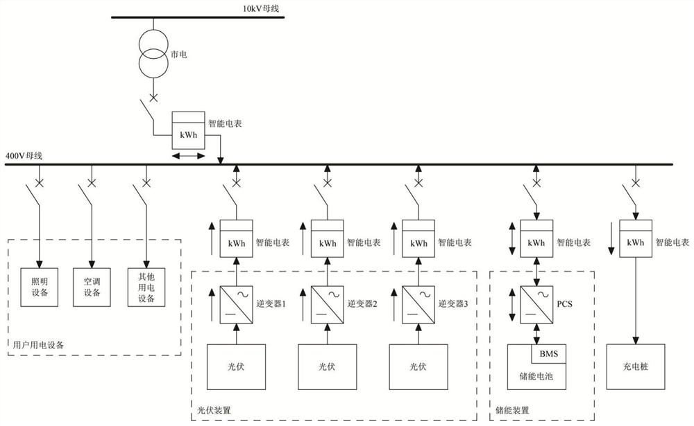
[0068] Embodiment one: as attached figure 1 As shown, the photovoltaic energy storage system connected to the grid includes photovoltaic devices, energy storage devices, and transformers. The mains power of the grid is connected to the 400V bus through the transformer, while the photovoltaic devices and energy storage It can also be connected to the user's electrical equipment, and a smart meter can be set between the grid and the 400V bus to detect power. The photovoltaic device includes a plurality of photovoltaic panels and a plurality of inverters connected to the photovoltaic panels one by one. In this embodiment, three photovoltaic panels and three inverters are taken as an example. into the 400V bus. The energy storage device includes an energy storage battery, a power storage converter (PCS) connected to the energy storage battery, and the energy storage converter is also connected to the 400V bus through a smart meter. The energy storage converter has a power-on sta...


PUM


Abstract

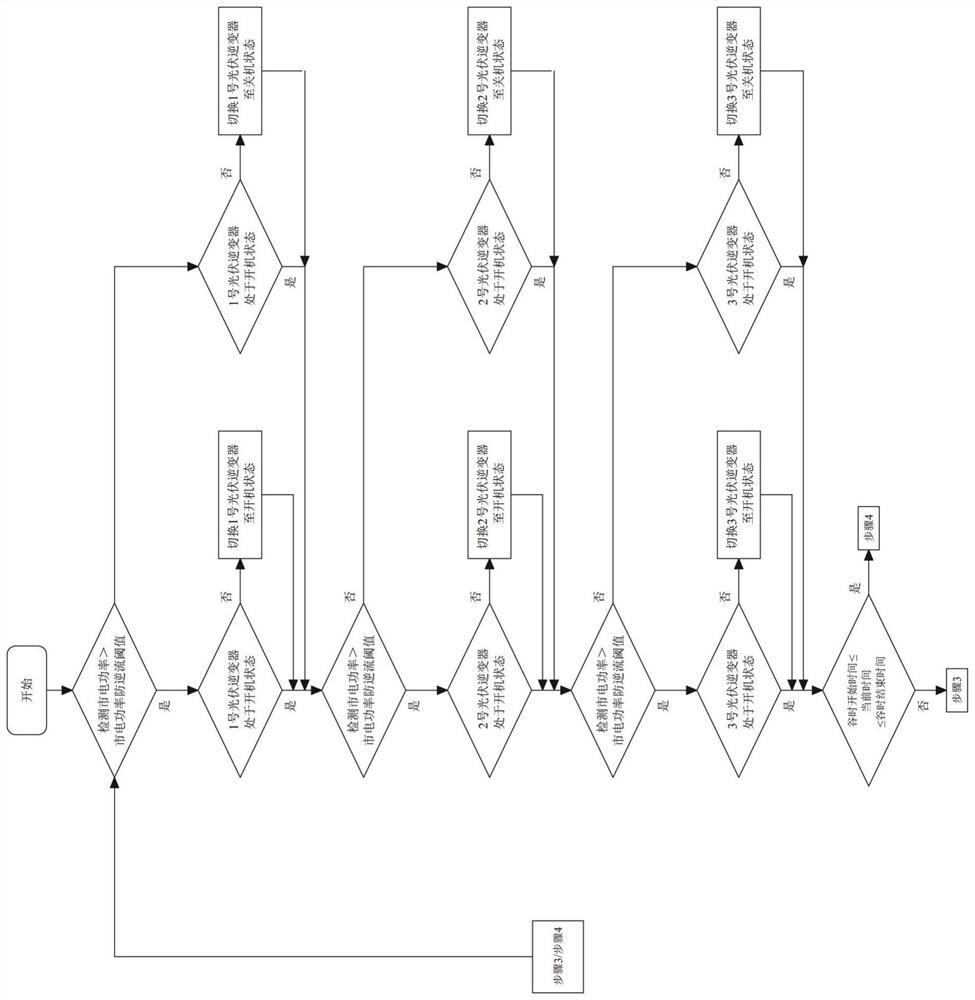
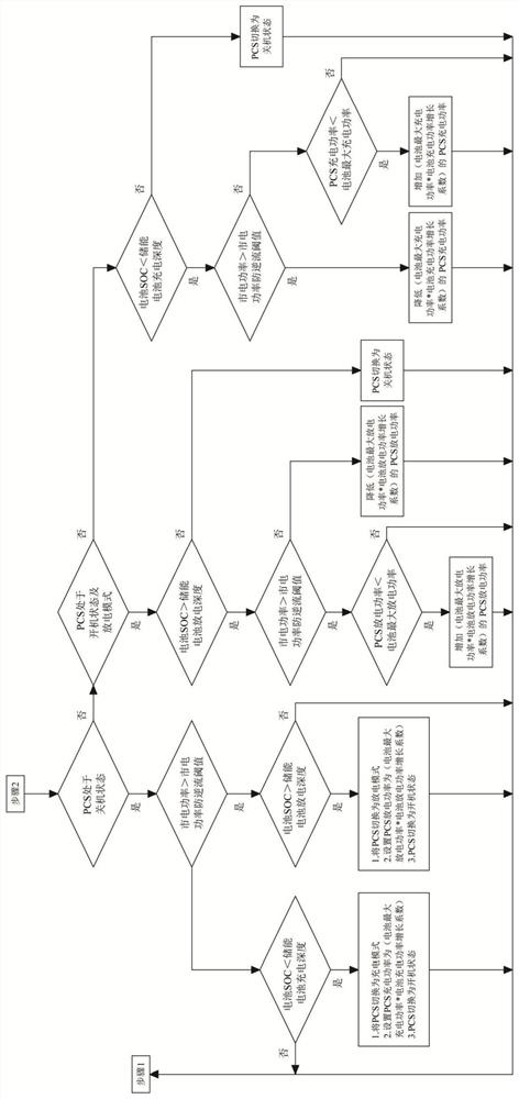
The invention relates to a photovoltaic energy storage cooperative operation control method, which comprises the following steps of: 1, judging whether reverse current exists between a photovoltaic energy storage system and a power grid or not, adjusting the working state of each inverter according to a judgment result, and then executing the step 2; 2, judging whether the current time is within a valley time period, if not, executing a step 3, and if so, executing a step 4; 3, judging whether countercurrent exists between the photovoltaic energy storage system and the power grid or not, and adjusting the charging power or the discharging power of an energy storage converter according to the judgment result under the constraint of the charging and discharging constraint conditions of an energy storage device; and 4, judging whether the energy storage device meets the charging and discharging constraint conditions of the energy storage device and the working constraint conditions of a transformer, if so, increasing the charging power of the energy storage converter, and if not, reducing the charging power of the energy storage converter. The power generation power and the charging and discharging power of the photovoltaic energy storage system can be adjusted in real time, and the problems of countercurrent and transformer overload are avoided.

Description

technical field [0001] The invention belongs to the technical field of micro-grid control, and in particular relates to a method suitable for controlling the coordinated operation of a photovoltaic energy storage system. Background technique [0002] As an important support of "Internet +" smart energy and a technical means of friendly interaction with the large power grid, the microgrid can improve the safety and reliability of the power system, promote the access and local consumption of clean energy, and improve energy utilization efficiency. It plays an important role in energy conservation and emission reduction, which is conducive to building a conservation-oriented society. [0003] At present, deep-seated contradictions such as low overall efficiency of the power system, insufficient coordination of sources, grids and loads, and insufficient complementarity and mutual assistance of various power sources have become increasingly prominent, and urgently need overall op...

Claims


Application Information

Patent Timeline
Patent Type & Authority Applications(China)
IPC IPC(8): H02J3/32H02J3/38H02J3/46
CPCH02J3/32H02J3/381H02J3/466H02J2300/24Y02E10/56Y02E70/30
Inventor 周玉朱卓敏
Owner SHANGHAI POWERSHARE TECH LTD
Learn More