
Power utilization control method and system for fuel cell test laboratory

A fuel cell and electrical control technology, which is applied in power network operating system integration, information technology support system, power generation forecast in AC network, etc. and other issues to ensure reliability and control the cost of electricity

Pending Publication Date: 2021-11-30
上海智能新能源汽车科创功能平台有限公司
View PDF0 Cites 0 Cited by
  • Summary
  • Abstract
  • Description
  • Claims
  • Application Information

AI Technical Summary

Problems solved by technology

Due to the upper limit of the laboratory's useful power, it is difficult to meet the peak use of hundreds of high-power test equipment at the same time. The cost of experimentation rises and a lot of resources are wasted

Method used


Image

  • Power utilization control method and system for fuel cell test laboratory
  • Power utilization control method and system for fuel cell test laboratory
  • Power utilization control method and system for fuel cell test laboratory

Examples


Embodiment 1

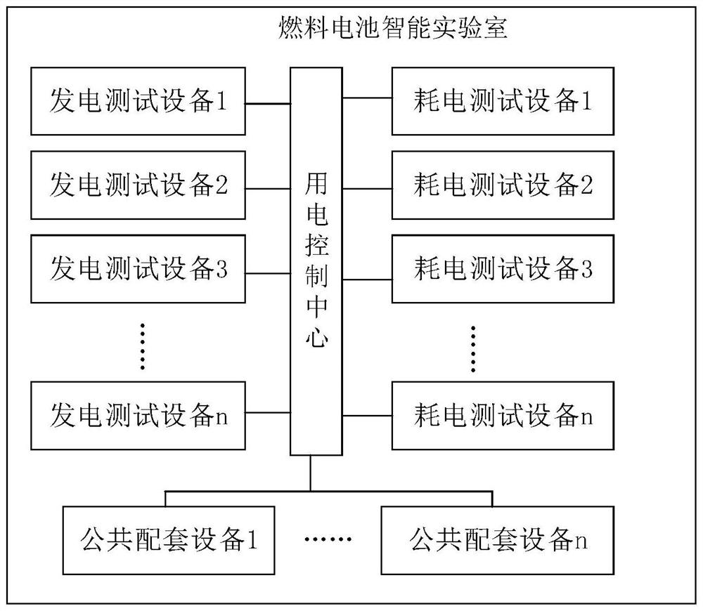
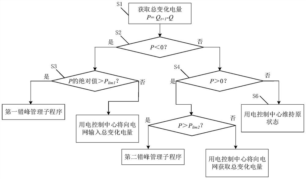
[0050] This embodiment provides a power consumption control method for a fuel cell testing laboratory, which is an emerging fuel cell intelligent laboratory. Such as figure 1 As shown, the test laboratory includes power generation test equipment, power consumption test equipment, some public supporting equipment and power consumption control center, power generation test equipment (such as fuel cell system test bench), power consumption test equipment (such as fuel cell stack test bench , sub-part test bench, etc.) and some public supporting equipment are connected to the power grid through the power control center. Under the management control of the power consumption control center, the power is dispatched between the equipment and the grid. Such as figure 2 As shown, the power consumption control method specifically includes:

[0051] Step S1. Obtain the current total power consumption Q of all devices running at the current moment t and the total power consumption Q o...

Embodiment 2

[0067] This embodiment provides a power consumption control system of a fuel cell testing laboratory, which is the power consumption control center of the testing laboratory. Such as Figure 5 As shown, it includes the acquisition module, the first judgment module, the second judgment module, the third judgment module, the fourth judgment module and the maintenance operation module. The details are as follows:

[0068] The collection module is used to obtain the current total power consumption Q of all devices running at the current moment t and the total power consumption Q of all equipment running at the next moment t+1, where when the power consumption is positive, it is the power consumption, and when the power consumption is negative, it is the output power, so the total variable power P=Q can be calculated t+1 -Q t .

[0069] The first judging module is used for judging whether the total variable electric quantity P<0 is satisfied, if so, the second judging module re...


PUM


Abstract

The invention relates to a power consumption control method and system for a fuel cell test laboratory. The method comprises the steps of obtaining the current total power consumption of all equipment operating at the current moment and the required total power consumption of all equipment operating at the next moment, and calculating the total change power consumption; judging whether the total change power consumption is less than 0 or not, if so, continuing to judge whether the absolute value of the total change power consumption exceeds the maximum load capacity set by the laboratory or not, and if so, executing a first peak shifting management subprogram; if not, enabling all the equipment to enter the operation state at the next moment; when the total change power consumption is greater than 0, continuing to judge whether the total change power consumption exceeds the maximum power consumption set by the laboratory, and if so, executing a second peak shifting management subprogram; and if not, enabling all the equipment to enter the operation state of the next moment. Compared with the prior art, the power utilization cost can be effectively controlled, the safety, continuity and stability of the fuel cell test system during working are ensured, and the reliability of a test result is ensured.

Description

technical field [0001] The invention relates to the field of fuel cell testing, in particular to a power consumption control method and system for a fuel cell testing laboratory. Background technique [0002] The Fuel Cell Smart Lab is an emerging laboratory for conducting various tests and experiments on fuel cells. The fuel cell intelligence laboratory has hundreds of high-power test equipment, including power consumption test equipment and public experiment equipment, as well as power generation test equipment. Due to the upper limit of the laboratory's useful power, it is difficult to meet the peak use of hundreds of high-power test equipment at the same time. Experimental costs rise and a lot of resources are wasted. Therefore, there is a need for a method that can effectively control the power supply of the fuel cell smart laboratory. Contents of the invention [0003] The object of the present invention is to provide a power consumption control method and system ...

Claims


Application Information

Patent Timeline
IPC IPC(8): H02J3/00G01R31/378G01R31/385
CPCH02J3/003H02J3/004G01R31/378G01R31/385H02J2310/60H02J2310/64Y02B70/3225Y04S20/222
Inventor 江正寒余卓平周向阳潘相敏杨秦泰崔明杰陈佳逸张若婧朱皓民任海平
Owner 上海智能新能源汽车科创功能平台有限公司
Learn More