
Laser power test system and test method

A technology of laser power and test system, applied in the laser field, can solve problems such as damage to the test module, affecting the test accuracy, and temperature increase of the test module

Pending Publication Date: 2021-11-30
HANS CNC SCI & TECH
View PDF0 Cites 0 Cited by
  • Summary
  • Abstract
  • Description
  • Claims
  • Application Information

AI Technical Summary

Problems solved by technology

[0003] The purpose of the embodiments of the present invention is to provide a laser power testing system, which is used to solve the technical problem that the laser irradiates the test module for a long time, which may easily cause the temperature of the test module to rise, affect the test accuracy, and even damage the test module.

Method used


Image

  • Laser power test system and test method
  • Laser power test system and test method
  • Laser power test system and test method

Examples


Embodiment Construction

[0045] Unless otherwise defined, all technical and scientific terms used herein have the same meaning as commonly understood by those skilled in the technical field of the present invention; the terms used in the specification herein are only for the purpose of describing specific embodiments, and are not intended to To limit the invention, for example, the terms "length", "width", "upper", "lower", "left", "right", "front", "rear", "vertical", "horizontal", "top ", "bottom", "inner", "outer" and other indicated orientations or positions are based on the orientations or positions shown in the drawings, which are only for convenience of description and cannot be understood as limitations on the technical solution.

[0046] The terms "include" and "have" in the specification and claims of the present invention and the description of the above drawings, as well as any variations thereof, are intended to cover a non-exclusive inclusion; The terms "first", "second", etc. are used t...


PUM


Abstract

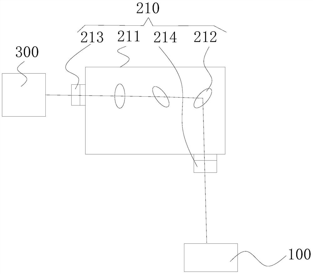
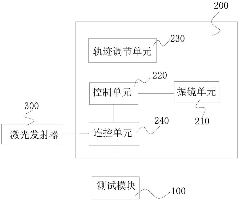
The invention belongs to the technical field of laser, and relates to a laser power test system and a test method. The laser power test system comprises a test module and a regulation and control module, the regulation and control module is used for receiving a test instruction for carrying out power test on a laser emitter to be tested, according to the test instruction, the focus of the laser emitted by the laser emitter to be tested is controlled to move on the test module; the test module is used for detecting the power of the received laser; the regulation and control module comprises a galvanometer unit and a control unit, the control unit is used for controlling the reflection angle of the galvanometer unit, and the control unit is in communication connection with the test module and is used for controlling movement of the test module. According to the laser power test system, the laser focus of the laser emitter moves on the test module so that the laser focus is prevented from staying at the fixed position of the test module for a long time to influence the test precision and even burn out the test module; according to the invention, the power of the laser emitter can be rapidly and accurately tested.

Description

technical field [0001] The invention relates to the field of laser technology, in particular to a laser power testing system and testing method. Background technique [0002] For laser processing equipment, such as laser cutters, before laser processing, the power test of the machine will be carried out to collect information such as laser power and spot size to select the optimal processing parameters. The traditional machine power test method is to shoot the outgoing laser on the test module of the machine and measure its average power. If the laser irradiates the test module for a long time, it will easily cause the temperature of the test module to rise, affect the test accuracy, and even damage the test module. Contents of the invention [0003] The purpose of the embodiments of the present invention is to provide a laser power testing system, which is used to solve the technical problem that the laser irradiates the test module for a long time, which may easily cause...

Claims


Application Information

Patent Timeline
Patent Type & Authority Applications(China)
IPC IPC(8): G01J1/00G01M11/02
CPCG01J1/00G01M11/02
Inventor 刘程荣林潇俊陈国栋吕洪杰翟学涛
Owner HANS CNC SCI & TECH
Learn More