Constant-tension cloth feeding mechanism for printing machine

A cloth feeding mechanism and constant tension technology, applied in mechanical cleaning, high pressure cleaning, textile and papermaking, etc., can solve the problems of easy wrinkling, poor printing, affecting product quality, etc., to achieve convenient tension, ensure flatness, The effect of high practicality

Pending Publication Date: 2021-11-30
长兴诺新纺织科技有限公司
View PDF0 Cites 0 Cited by
  • Summary
  • Abstract
  • Description
  • Claims
  • Application Information

AI Technical Summary

Problems solved by technology

However, the cloth feeding mechanism used in advertising printing equipment cannot adjust the cloth feeding tension according to the properties of the fabric during the cloth feeding process, and cannot adapt to the requirements of diversified fabrics. For elastic fabrics, it is very easy to wrinkle during the cloth feeding and printing process, resulting in poor printing.
Moreover, the existing cloth feeding mechanism cannot remove lint from the fabric when feeding the cloth, which affects product quality.

Method used


Image

  • Constant-tension cloth feeding mechanism for printing machine
  • Constant-tension cloth feeding mechanism for printing machine
  • Constant-tension cloth feeding mechanism for printing machine

Examples


Embodiment 1

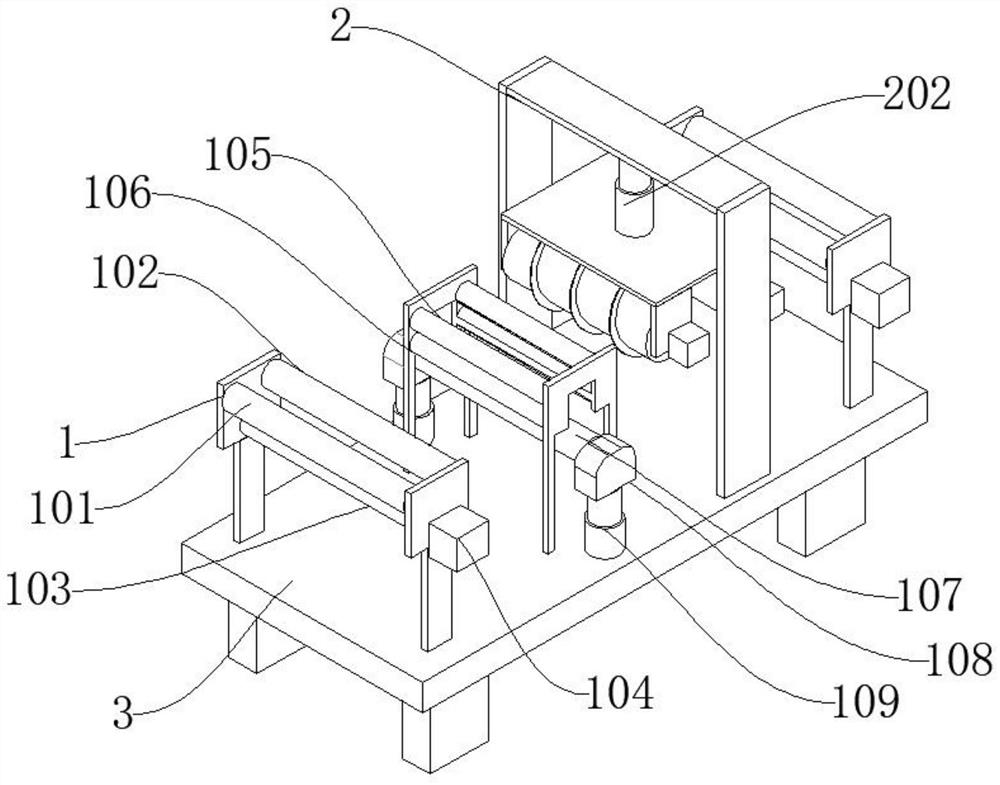
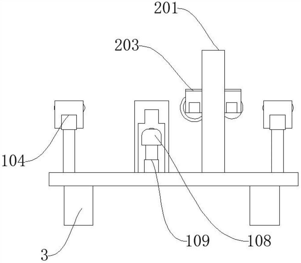
[0025] Such as figure 1 , figure 2 , image 3 , Figure 4 As shown, the present invention provides a technical solution: a constant tension cloth feeding mechanism for printing machines, including a base 3, a transmission mechanism 1 is arranged on the base 3, a cleaning mechanism 2 is arranged on one side of the transmission mechanism 1, and the transmission mechanism 1 includes a Conducting column 101, No. 2 conducting column 102, No. 3 conducting column 103, No. 2 conducting column 102 is arranged on one side of No. 1 conducting column 101, No. 3 conducting column 103 is arranged under No. 1 conducting column 101, and No. 3 conducting column 103 No. 1 motor 104 is installed at the top, No. 2 conducting column 102 is provided with an upper guide roller 105 away from No. 1 conducting column 101, a lower guide roller 106 is installed below the upper guide roller 105, and an adjusting roller 107 is arranged below the lower guide roller 106. Mounting seat 108 is installed on...

Embodiment 2

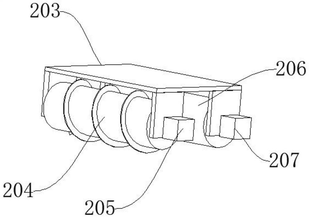
[0029] Such as Figure 5 As shown, the difference between Embodiment 2 and Embodiment 1 is that the cleaning mechanism 2 includes a support 201, No. 2 electric telescopic column 202, and a mounting frame 203, and No. 2 electric telescopic column 202 is installed on the inside of support 201, and No. 2 electric telescopic column 202 Mounting frame 203 is installed on the lower end, and carding roller 204 is installed in mounting frame 203 inner side, and No. 2 motor 205 is installed on carding roller 204 front, and electrostatic adsorption net 208 is installed on carding roller 204 one side.

[0030] No. 3 motor 207 is driven to stick the hair roller 206 to rotate, stick the fluff on the cloth, and replace it with the electrostatic adsorption net 208 to absorb the fluff on the cloth passing below.


PUM


Abstract

The invention discloses a constant-tension cloth feeding mechanism for a printing machine. The constant-tension cloth feeding mechanism comprises a base, a conveying mechanism is arranged on the base, a cleaning mechanism is arranged on one side of the conveying mechanism, the conveying mechanism comprises a first conduction column, a second conduction column and a third conduction column, the second conduction column is arranged on one side of the first conduction column, the third conduction column is arranged below the first conduction column, a first motor is installed on the front portion of the third conduction column, an upper guide roller is arranged on the side, away from the first conduction column, of the second conduction column, and a lower guide roller is installed below the upper guide roller. The constant-tension cloth feeding mechanism for the printing machine is simple in structure, reasonable in design, low in production cost, the tensioning force of cloth is greatly convenient to adjust, meanwhile, batting on the cloth can be effectively removed, the flatness of the cloth is guaranteed, and the product quality is improved.

Description

technical field [0001] The invention relates to the technical field of printing machines, in particular to a constant tension cloth feeding mechanism for printing machines. Background technique [0002] At present, most digital printing cloth feeding mechanisms use the paper feeding mechanism of advertising printing equipment. Since the nature of advertising paper is relatively stable, the elasticity does not change much, and the requirements for paper feeding are not high. However, there are many kinds of fabrics used in digital printing, including knitted, woven, non-elastic, single-sided elastic, double-sided elastic, etc. However, the cloth feeding mechanism used in advertising printing equipment cannot adjust the cloth feeding tension according to the properties of the fabric during the cloth feeding process, and cannot adapt to the requirements of diversified fabrics. For elastic fabrics, it is very easy to wrinkle during the cloth feeding and printing process, result...

Claims


Application Information

Patent Timeline
Patent Type & Authority Applications(China)
IPC IPC(8): B65H23/26D06G1/00
CPCB65H23/26D06G1/00B65H2701/174
Inventor 王敏新
Owner 长兴诺新纺织科技有限公司
Why Eureka
Try Eureka