Automatic liquid supply device for municipal landscaping seedling culture
A landscaping and liquid supply technology, applied in the field of garden seedling raising, can solve problems such as the inability to freely control the liquid outflow rate and the influence of seedling survival rate, and achieve the effect of improving the controllability of water flow rate, avoiding uneven spraying and consistent water pressure.
- Summary
- Abstract
- Description
- Claims
- Application Information
AI Technical Summary
Problems solved by technology
Method used
Image
Examples
Embodiment 1
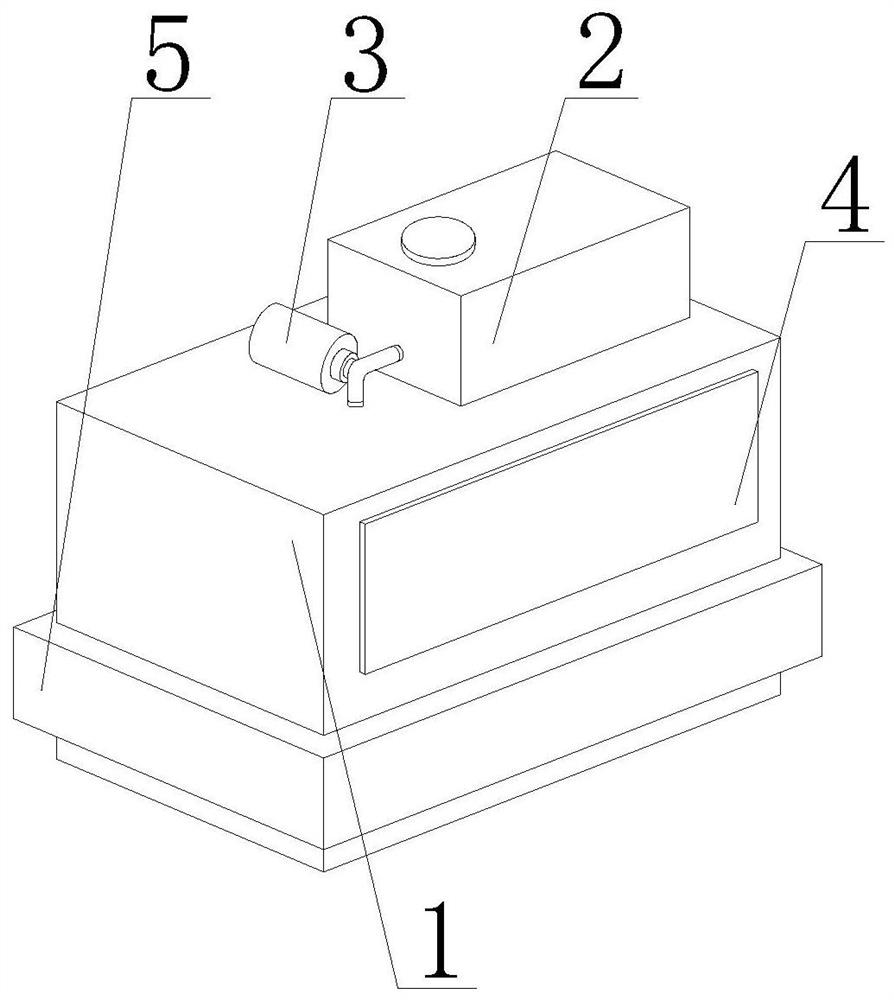
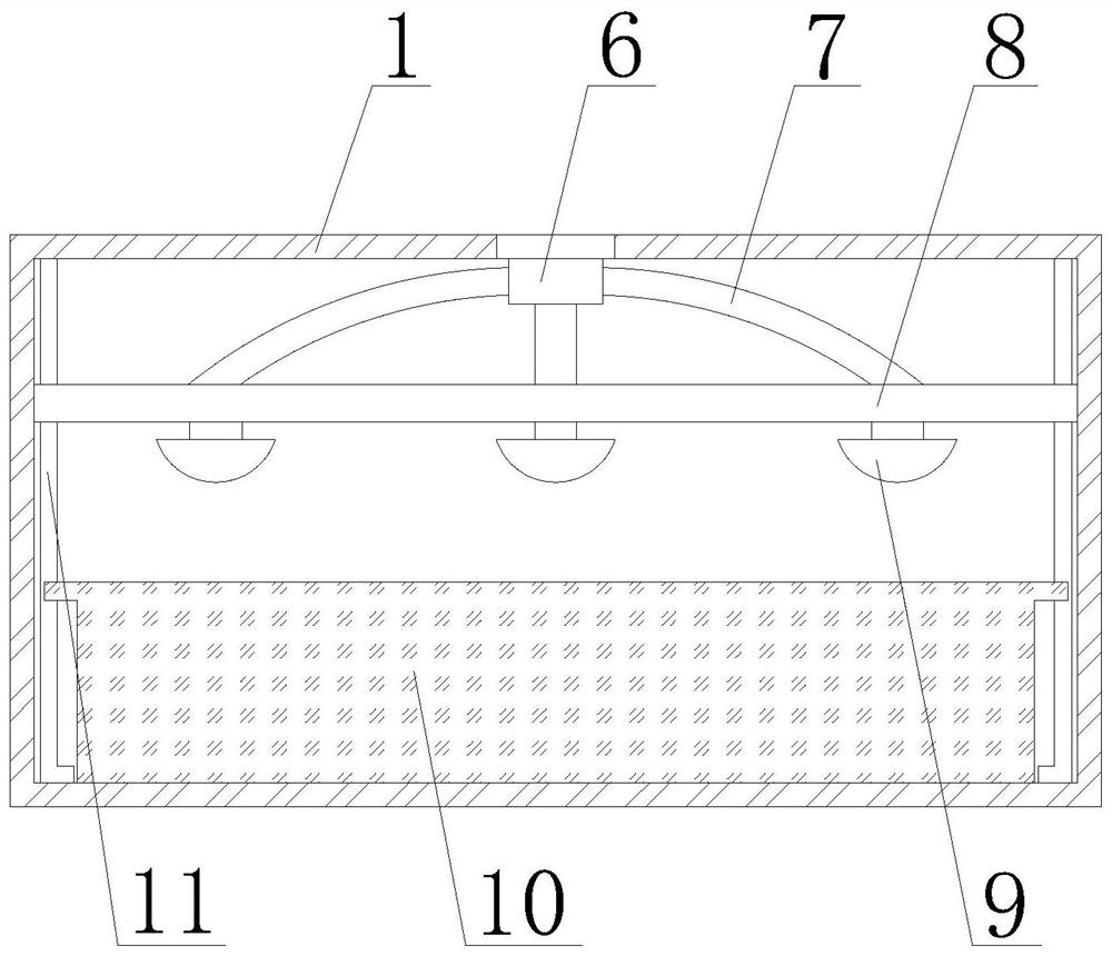
[0028] Such as Figure 1-Figure 6 Shown, the present invention provides a kind of municipal landscaping seedling raising automatic liquid supply device, comprises seedling raising box 1, water storage tank 2, air pump 3, perspective window 4 and electric wire heating belt 5, the outer wall of seedling raising box 1 and The inner wall of the electric wire heating belt 5 is fixedly connected, the top of the seedling raising box body 1 is fixedly connected with the bottom of the water storage tank 2, the output end of the air pump 3 is connected through the inner wall of the seedling raising box body 1, and the outer wall of the perspective window 4 is connected with the seedling raising box body The inner wall of 1 is embedded and connected, and the inner wall of the seedling raising box 1 is provided with a shunt pipe 6, a flow pipe 7, an adjustment plate 8, a spray liquid supply device 9, a seedling placement box 10 and a slide bar 11, and the top of the shunt pipe 6 It is fix...
Embodiment 2
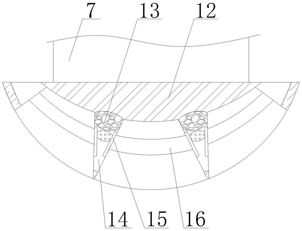
[0031] Such as Figure 3-4As shown, on the basis of Embodiment 1, the present invention provides a technical solution: the spray liquid supply device 9 includes a manifold 12, an air pressure bag 13, a reserved cavity 14, an adjustment rod 15 and a liquid supply adjustment pipe 16, The top of the manifold 12 is sealed and connected to the bottom of the manifold 7, the top of the air pressure bag 13 is overlapped with the bottom of the manifold 12, and the two ends of the liquid supply regulating pipe 16 are fixedly connected to the inner wall of the spray liquid supply device 9 The reserved chamber 14 is located on the inner wall of the spray liquid supply device 9, and one side of the adjustment rod 15 is fixedly connected with the inner wall of the reserved chamber 14. When the water supply pipe 7 delivers water to the inside of the manifold 12, due A large amount of water stays inside the manifold 12 so that the air pressure bag 13 is deformed downward by the pressure of th...
Embodiment 3
[0033] Such as image 3 , Figure 5 , Image 6 As shown, on the basis of Embodiment 1 and Embodiment 2, the present invention provides a technical solution: preferably, the liquid supply adjustment tube 16 includes a microporous tough bag 20, a microporous sleeve 21, an embedded tube 22, and a guide plate 23. The spray device 24 and the follower plate 25, the two ends of the microporous tough bag 20 are fixedly connected to the outer wall of the adjustment rod 15, the outer wall of the embedded tube 22 is slidably connected to the inner wall of the microporous casing 21, and the microporous casing 21 The top of the top is fixedly connected with the lower right end of the guide plate 23, the upper left end of the guide plate 23 is fixedly connected with the right side of the adjustment rod 15, the top of the spray device 24 is connected through the bottom of the microporous casing 21, and the follower plate 25 The right side is fixedly connected with the left side of the embe...
PUM
 Abstract
Description
Claims
Application Information
 - R&D
- Intellectual Property
- Life Sciences
- Materials
- Tech Scout
- Unparalleled Data Quality
- Higher Quality Content
- 60% Fewer Hallucinations
Browse by: Latest US Patents, China's latest patents, Technical Efficacy Thesaurus, Application Domain, Technology Topic, Popular Technical Reports.
© 2025 PatSnap. All rights reserved.Legal|Privacy policy|Modern Slavery Act Transparency Statement|Sitemap|About US| Contact US: help@patsnap.com


