Central control box with multiple auxiliary functions

A technology for auxiliary functions and control boxes, which is applied to electrical components, substation/power distribution device shells, substation/switch layout details, etc., which can solve installation troubles, construction personnel's sweat dripping inside the box, and affect construction personnel's installation speed and efficiency issues

Pending Publication Date: 2021-11-26
徐州瑞格电子有限公司
View PDF0 Cites 1 Cited by
  • Summary
  • Abstract
  • Description
  • Claims
  • Application Information

AI Technical Summary

Problems solved by technology

[0003] The object of the present invention is to provide a kind of central control box with multiple auxiliary functions for the deficiencies of the prior art, to solve the existing central control box proposed in the above background technology because the internal space is deep and will need When the power control and electric control are installed inside the box, half of the construction personnel's body needs to be inserted into the box for installation. Since the inner space of the box is in a semi-closed state, it will not only affect the safety of the construction workers when the weather is hot. The installation speed and efficiency are also likely to cause the sweat of the construction workers to drip inside the box. In turn, the overall height of the existing box is relatively high, so when installing the power control and power control above the box, it is necessary to use auxiliary climbing tools for auxiliary installation. , which not only causes installation troubles but also affects the mobile handling of construction personnel during work

Method used


Image

  • Central control box with multiple auxiliary functions
  • Central control box with multiple auxiliary functions
  • Central control box with multiple auxiliary functions

Examples


Embodiment Construction

[0039] The following will clearly and completely describe the technical solutions in the embodiments of the present invention with reference to the accompanying drawings in the embodiments of the present invention. Obviously, the described embodiments are only some, not all, embodiments of the present invention. Based on the embodiments of the present invention, all other embodiments obtained by persons of ordinary skill in the art without making creative efforts belong to the protection scope of the present invention.

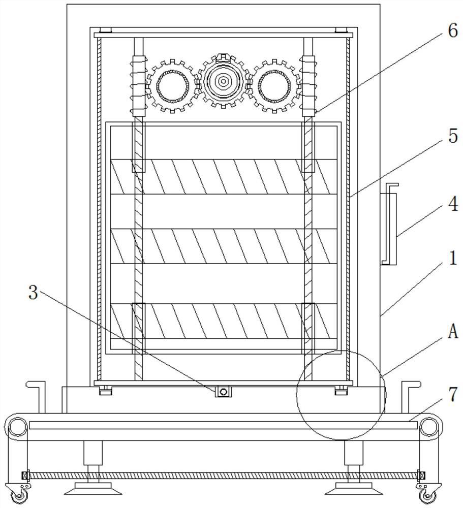
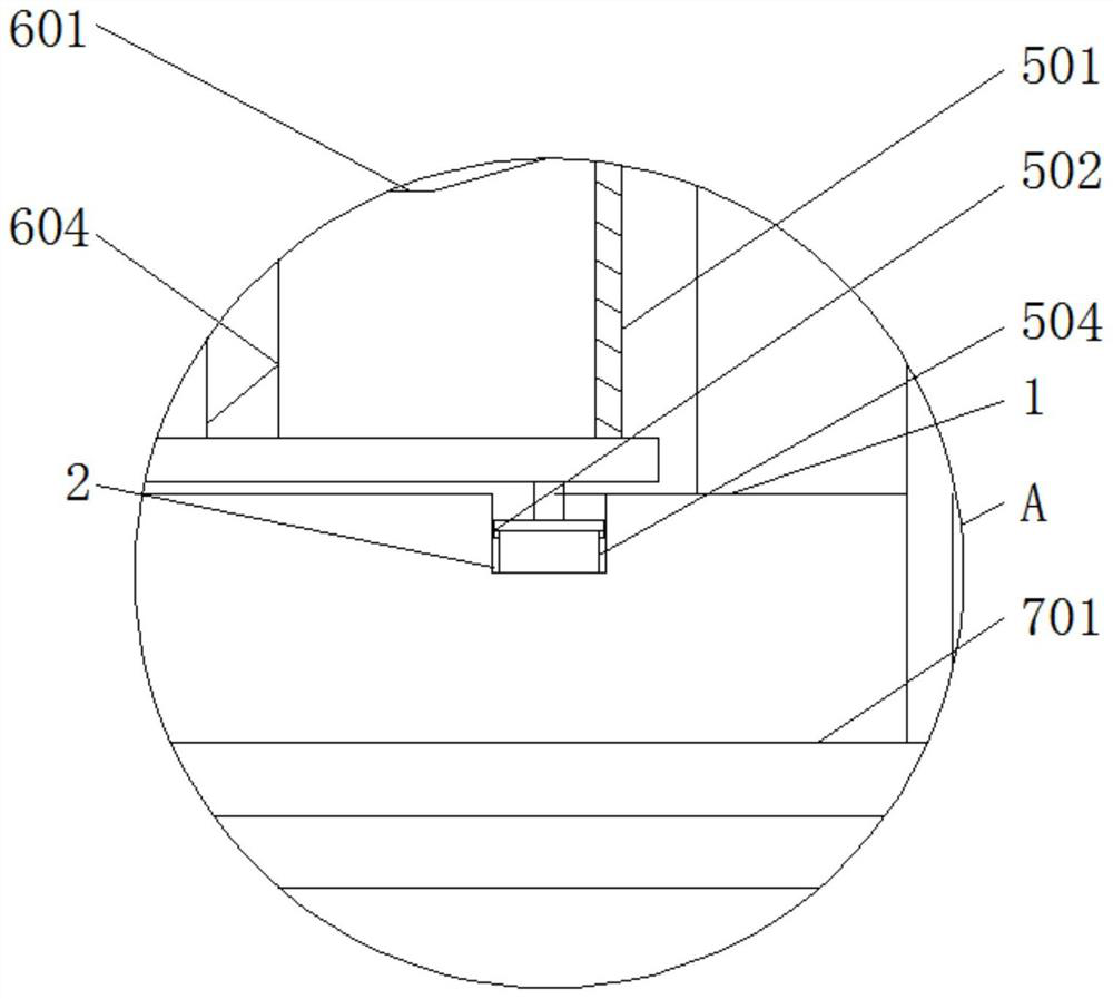
[0040] see Figure 1-8 , the present invention provides a technical solution: a central control box with multiple auxiliary functions, such as figure 1 and figure 2 As shown, there are first installation grooves 2 on both sides of the bottom of the box body 1, and a second installation groove 3 is opened on the bottom of the box body 1. At the same time, a box 4 is fixed on one side of the box body 1. By placing the box 4, it is convenient The crank 507 is ...


PUM


Abstract

The invention discloses a central control box with multiple auxiliary functions. The central control box comprises a box body, a movable mounting mechanism, a lifting adjusting mechanism and a movable matching device, first mounting grooves are formed in two sides of the lower part in the box body, a second mounting groove is formed in the lower part in the box body, a storage box is fixed on one side of the box body, the movable mounting mechanism is installed in the box body and comprises a connecting plate, a sliding block set, a screw block, a sliding rail set, a first screw rod, a matched pin and a crank, and the upper portion of the connecting plate is fixedly connected with one end of the sliding block set. The central control box with multiple auxiliary functions is provided with the first mounting grooves, one side of the sliding rail set is conveniently mounted in the first mounting grooves through the first mounting grooves, and the relative distance height between one side of the sliding rail set and the lower part in the box body is reduced through the first mounting grooves, so that not only is the transverse mounting length of a second screw rod increased, but also the vertical mounting length of the connecting plate is increased.

Description

technical field [0001] The invention relates to the technical field of central control boxes, in particular to a central control box with various auxiliary functions. Background technique [0002] The central control box is an integrated cabinet mostly used in power control, electric control and other fields. It is often designed with various electrical components inside. However, the existing central control box will need to install a power control box due to its deep internal space When the power control is installed inside the box, half of the construction personnel's body needs to be inserted into the box for installation. Since the interior space of the box is in a semi-closed state, it will not only affect the installation speed and efficiency of the construction personnel when the weather is hot It is also easy to cause construction workers' sweat to drip inside the box body, and the overall height of the existing box body is relatively high, so that when installing t...

Claims


Application Information

Patent Timeline
Patent Type & Authority Applications(China)
IPC IPC(8): H02B1/46H02B1/48H02B1/28H02B1/50H02B1/52
CPCH02B1/46H02B1/48H02B1/28H02B1/50H02B1/52
Inventor 刘亚林朱新红郑友来
Owner 徐州瑞格电子有限公司
Why Eureka
Try Eureka