
Portable foundation pit and side slope gradient control device and control method

A slope control, portable technology, applied in measuring devices, control without feedback, measuring instruments, etc., can solve the problems of inconvenient height adjustment, inconvenient storage and protection of laser instruments, etc. Effect

Active Publication Date: 2021-11-26
SHANDONG ZHENGYUAN CONSTR ENG
View PDF11 Cites 0 Cited by
  • Summary
  • Abstract
  • Description
  • Claims
  • Application Information

AI Technical Summary

Problems solved by technology

[0009] A portable foundation pit and slope slope control device and control method proposed by the present invention solve the problems of inconvenient storage and protection of laser instruments, precise adjustment of inclination angle, height adjustment, and inconvenient quick and automatic leveling of angle discs

Method used


Image

  • Portable foundation pit and side slope gradient control device and control method
  • Portable foundation pit and side slope gradient control device and control method
  • Portable foundation pit and side slope gradient control device and control method

Examples


Embodiment 1

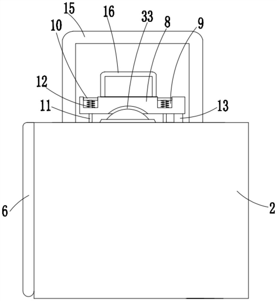
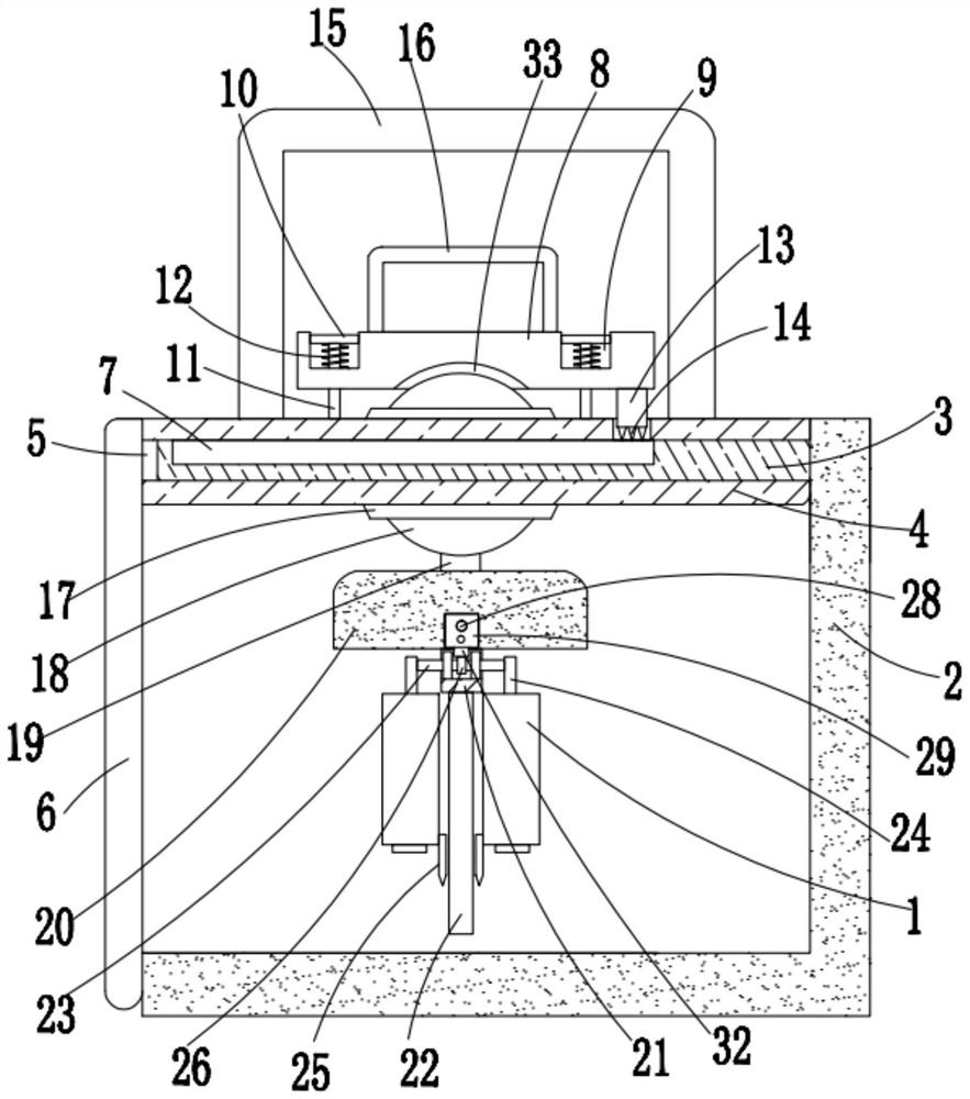
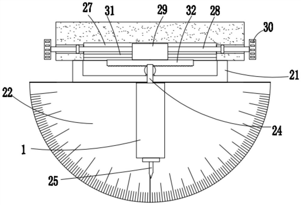
[0041] refer to Figure 1-5 , a portable foundation pit and slope slope control device, including a protective box 2 with openings on the top and left sides, two laser instruments 1 are arranged in the protective box 2, and movable contacts on the right inner wall of the protective box 2 Top plate 4, the left side of top plate 4 is fixedly connected with baffle plate 6, the right side of baffle plate 6 is in movable contact with the left side of protective box 2, and the right side of top plate 4 is provided with two rectangular holes 5, and the top inner wall of rectangular hole 5 There is a penetration hole on the top, and the sliding sleeve in the rectangular hole 5 is provided with a guide rod 3. The right ends of the two guide rods 3 are fixedly connected with the right inner wall of the protective box 2, and the guide rod 3 cooperates with the rectangular hole 5. Left and right guide support, the top of the guide rod 3 is provided with an embedded groove, and a hard anti...

Embodiment 2

[0053] refer to Figure 6-8 , the present embodiment is based on the first embodiment, and its difference from the first embodiment is that: the protective box 2 is also provided with a height adjustment mechanism, the height adjustment mechanism includes a bottom plate 44 that is in movable contact with the bottom of the protective box 2, and The top right side of the bottom plate 44 is fixedly connected with a rectangular inner tube 34 whose top is a plugging mechanism. The top of the rectangular inner tube 34 extends into the protective box 2. The rectangular inner tube 34 is slidingly sleeved with a rectangular outer tube 35. The rectangular outer tube The top of 35 is fixedly connected with the rectangular box 36 that the right side is that opening is provided with, and the right side of rectangular box 36 is fixedly connected with the right side inner wall of protective box 2, and the inner sliding sleeve of rectangular inner tube 34 is provided with rectangular seat 37, ...


PUM


Abstract

The invention provides a portable foundation pit and side slope gradient control device and a control method, and provides the following scheme aiming at the problems that according to an existing gradient control device, a laser instrument cannot be stored and protected conveniently, the inclination angle and the height cannot be adjusted accurately, and an angle measuring disc cannot be leveled rapidly and automatically. The invention provides the following scheme: the gradient control device comprises a protection box with the top and the left side opened, two laser instruments are arranged in the protection box, the inner wall of the right side of the protection box is movably in contact with a top plate, and the left side of the top plate is fixedly connected with a baffle. According to the invention, the laser instrument can be conveniently stored and protected, the risk that the laser instrument is accidentally touched and damaged when the laser instrument is not used or carried is reduced, the laser instrument and the semicircular angle measuring disc can be conveniently and rapidly unlocked and moved out, the semicircular angle measuring disc can be automatically and rapidly leveled while the laser instrument and the semicircular angle measuring disc are moved out, the inclination angle of the laser instrument can be rapidly and accurately adjusted, the indication precision during slope making is improved, and the height of the laser instrument can be conveniently adjusted according to actual needs.

Description

technical field [0001] The invention relates to the technical field of slope control equipment, in particular to a portable foundation pit and side slope slope control device and control method. Background technique [0002] When grading foundation pits and slopes, it is necessary to accurately control the slope of the grading according to actual needs. The existing control methods mostly use two methods: pull rope and laser beam. Since the pull rope is used on some long slopes It is prone to loosening or breaking. Therefore, for such slopes, laser rays are often used to control the angle of the slope. The laser rays are used to indicate the angle of the slope. When grading, personnel can refer to the inclined laser rays for release. slope. [0003] The existing slope slope control device is composed of a laser instrument, a support frame and a measuring angle plate fixed on the support frame. Its operation method is to use a spirit level to measure the levelness of the sup...

Claims


Application Information

Patent Timeline
IPC IPC(8): G01C15/00G05D3/10
CPCG01C15/00G05D3/10Y02A10/23
Inventor 彭波吕海滨马明强刘世强李坤赵青海董宜辉李静
Owner SHANDONG ZHENGYUAN CONSTR ENG
Learn More