Safe medicament injection apparatus for medical treatment and push bar assembly for medicament injection for medical treatment

A technology of safe injection and assembly, applied in the direction of syringes, hypodermic injection devices, and devices introduced into the body, etc., can solve the problems of difficulty in improving the pass rate and output, difficult to operate, and small allowable range, so as to improve reliability and quality Stability, reduce accidental collision damage, and facilitate personnel operation

Active Publication Date: 2008-04-02
BENCHA INT GROUP
View PDF2 Cites 4 Cited by
  • Summary
  • Abstract
  • Description
  • Claims
  • Application Information

AI Technical Summary

Problems solved by technology

[0004] However, the above-mentioned breakable retractable push rod has high requirements on the symmetry and precision of the fractured part of the push rod in consideration of the force applied and the operability of personnel, which leads to the dimensional error of the mold used for integral injection molding in the production process of the push rod. The allowable range is very small, and it is difficult to prevent the breakage of the push rod during the assembly and handling process, so it is difficult to increase the pass rate and output, and the mold cost cannot be reduced
Furthermore, since the precise design of the fractured part of the push rod needs to cooperate with the effective angle of force to exert the safe retraction function, therefore, when the drug injection site belongs to a relatively curved or delicate organ of the human body, such as the head, behind the ear, In the eyes, mouth and other parts, it is not only difficult for medical staff to inject with one hand, but it is also more likely to inadvertently damage the function of the syringe due to the limited injection angle and difficult operation, causing discomfort to the patient

Method used


Image

  • Safe medicament injection apparatus for medical treatment and push bar assembly for medicament injection for medical treatment
  • Safe medicament injection apparatus for medical treatment and push bar assembly for medicament injection for medical treatment
  • Safe medicament injection apparatus for medical treatment and push bar assembly for medicament injection for medical treatment

Examples


Embodiment Construction

[0069] The implementation of the present invention is described below through specific specific examples, and those skilled in the art can easily understand other advantages and effects of the present invention from the content disclosed in this specification. The present invention can also be implemented or applied through other different specific embodiments, and various modifications and changes can be made to the details in this specification based on different viewpoints and applications without departing from the spirit of the present invention.

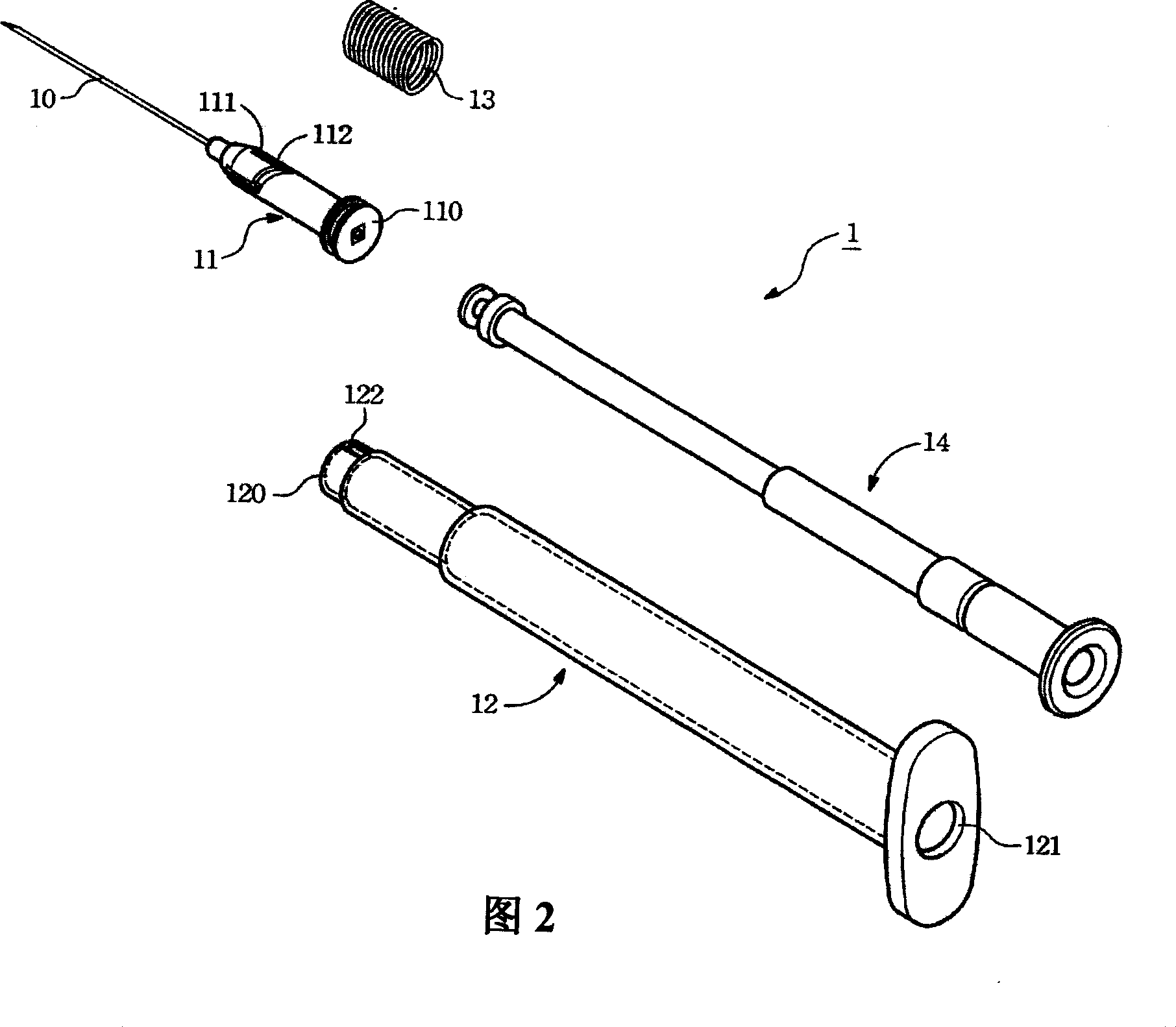
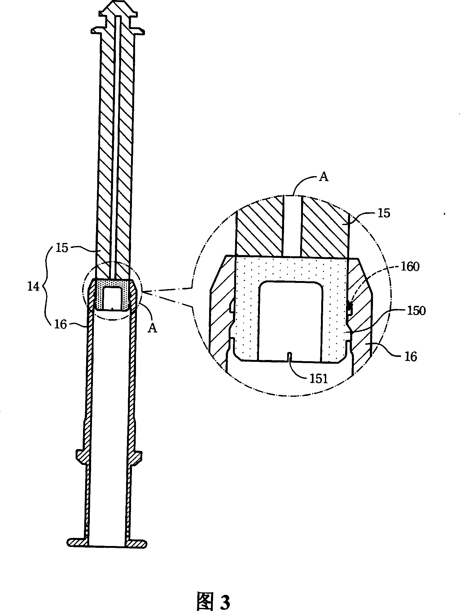
[0070] Fig. 2, Fig. 3 and Fig. 4 respectively represent the automatic retractable medical drug safety injection device ( Automatically Retractable Medically Safety Injector), and the three-dimensional and cross-sectional schematic diagrams of each part of the push rod assembly (Plunger combination) in the device. It should be noted that these drawings are all simplified schematic diagrams, and only illustrate preferred embodime...


PUM


Abstract

A medical medicine safety injection device includes a needle seat connected with a needle head, a hollow cartridge and push rod assembly components; the hollow cartridge can lock and hold the needle seat, and lead the needle seat after injection to retract into the cartridge; the push rod assembly components comprise a retraction rod and a hollow rod partially sleeve jointed with the retraction rod; the outer side wall of an area of the retraction rod sleeve jointed with the hollow rod is provided with at least a convex part, to be correspondingly clipped with at least a concave part formed on the inner side wall of the hollow rod. When the medical medicine injection device finishes injection and the user keeps stressing on the push rod assembly components, the retraction rod homoeopathically retracts into the hollow rod to spare the space in the cartridge originally for containing the retraction rod to contain the needle seat, so as to improve the operationality for the medical staff to inject with one hand.

Description

technical field [0001] The invention relates to a drug injection device, in particular to a safety injection device for medical drug injection and a push rod assembly thereof. Background technique [0002] In traditional drug injection, in order to reduce the risk of cross-infection diseases such as AIDS, hepatitis B, hepatitis C, etc., prevent drug addicts from reusing, and prevent medical staff from being accidentally stabbed with needles during injection, currently Most of the widely used injection syringes adopt a non-reusable safety design, that is, a disposable syringe (Disposable Syringe) that is destroyed after one use. However, this disposable safety syringe is designed to be convenient for the user to apply force when injecting, and it is often necessary to hold it at a fixed angle with both hands in operation to inject. In this way, when diabetic patients need to inject insulin (Insulin) by themselves and cannot operate the syringe with both hands at the same tim...

Claims


Application Information

Patent Timeline
IPC IPC(8): A61M5/315A61M5/32A61M5/50
CPCA61M5/3234A61M2005/31506A61M5/315A61M5/50
Inventor 林李李
Owner BENCHA INT GROUP
Why Eureka
Try Eureka