Drainage guiding device for department of cardiology
A guiding device and cardiology technology, applied in medical science, suction equipment, inoculation and ovulation diagnosis, etc., can solve the problems of lack of functional equipment such as quantitative liquid collection and periodic needle withdrawal, and achieve simple structure, easy operation, and strong practicability Effect
- Summary
- Abstract
- Description
- Claims
- Application Information
AI Technical Summary
Problems solved by technology
Method used
Image

Examples
Embodiment 1
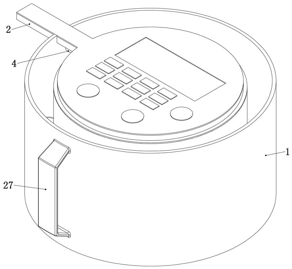
[0054] Embodiment 1, the present invention is a drainage guide device for cardiology, which is characterized in that it includes a casing 1 and a suction chamber 2, the casing 1 is a hollow topless cylindrical structure, which is used to provide a fixed foundation for subsequent structures, and the casing 1 The inner part is fixedly connected with a concentric cylinder partition, and the follow-up structure can be installed in the concentric cylinder partition. The liquid suction chamber 2 is detachably connected to the upper end of the shell 1, and one end of the liquid suction chamber 2 can be connected with the puncture needle. Detachable connection;
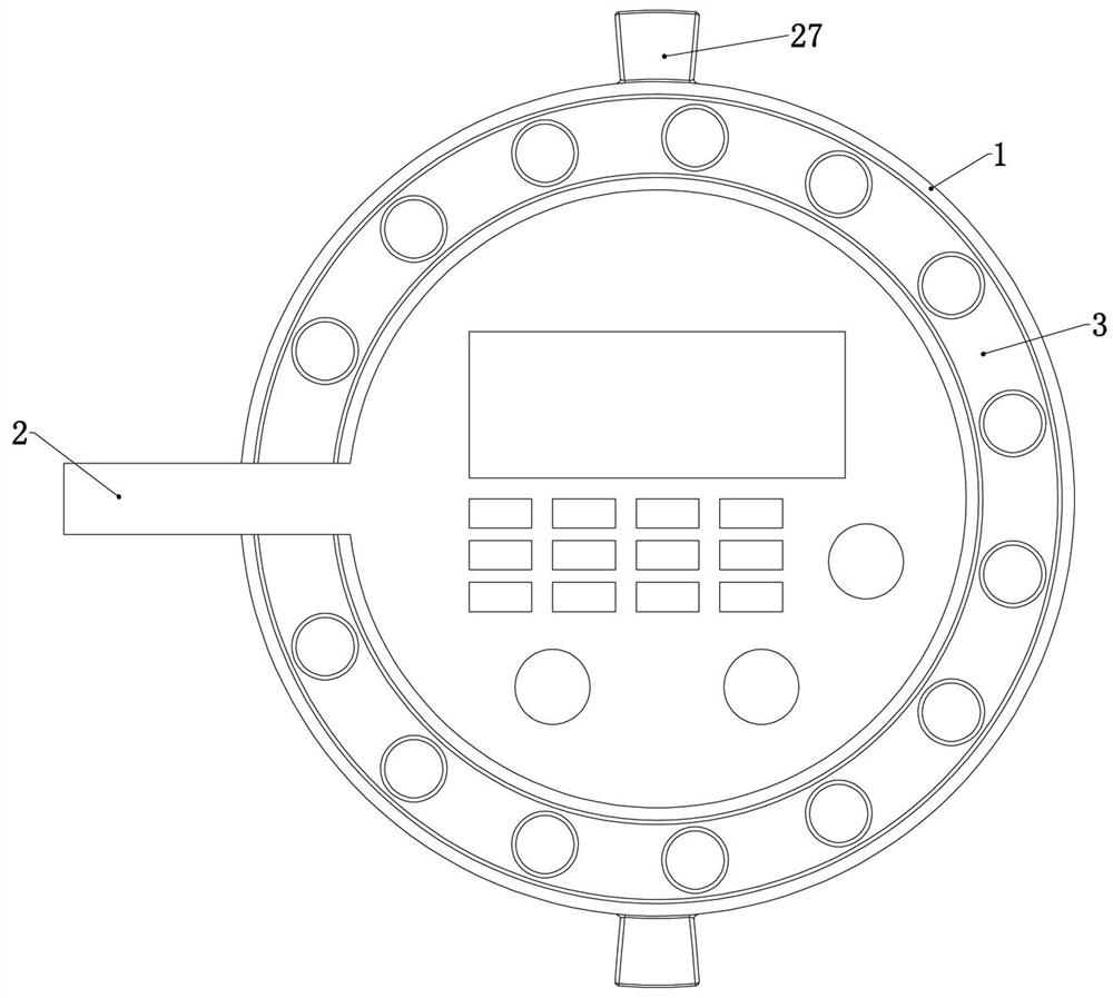
[0055] Carrying ring 3: The carrying ring 3 is rotatably connected in the housing 1, a number of vacuum liquid-taking tubes are detachably installed on the carrying ring 3, and the carrying ring 3 is rotatably connected to the concentric cylinder partition In addition, several fixing grooves are fixedly connected to the beari...
Embodiment 2
[0062] Embodiment 2, on the basis of Embodiment 1, the control module includes a piston drive unit for executing the piston long stroke step and the piston short stroke step;
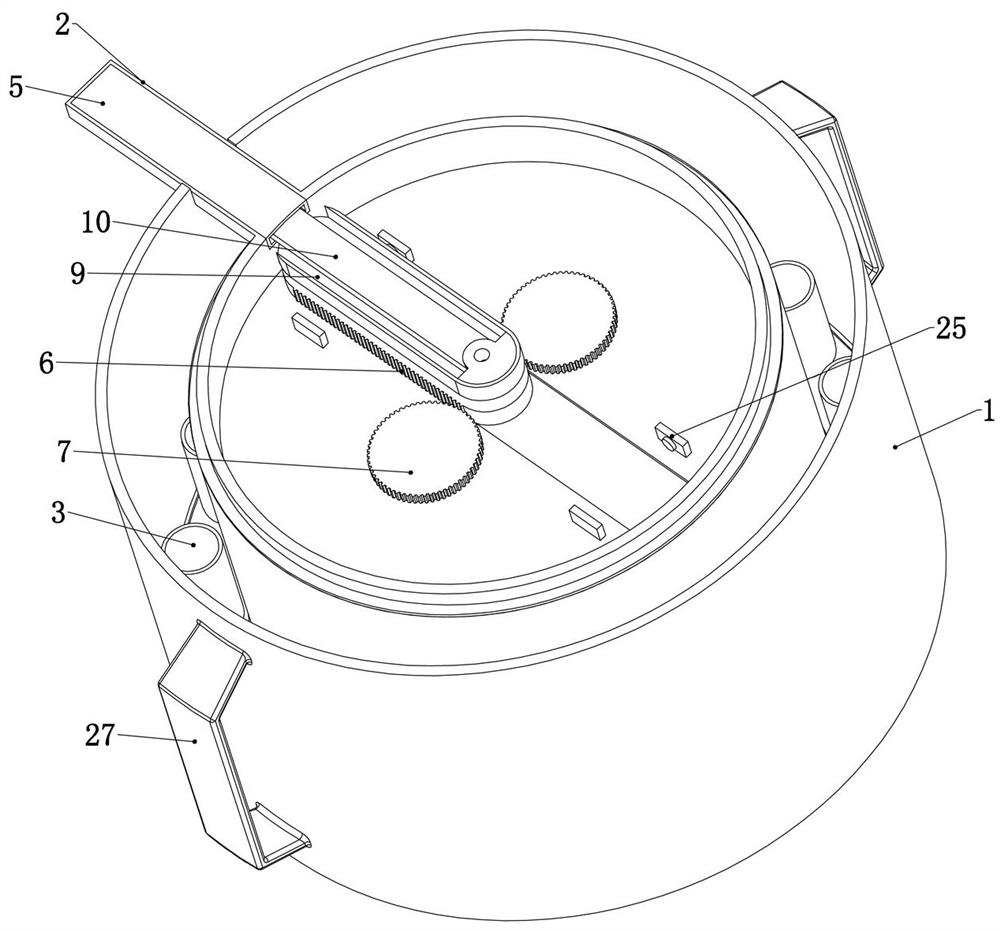
[0063] refer to image 3 , Figure 6 , the piston driving structure includes a piston rack 6 slidably connected in the housing 1, and both sides of the piston rack 6 are meshed with a piston driven gear 7 that is rotatably connected in the housing 1, and the piston The rotation of the driven gear 7 can drive the piston rack 6 to move, and the two piston driven gears 7 are meshed with the same piston drive gear 8 that is rotatably connected in the housing 1 through a gear transmission structure, so that the two pistons Piston driven gear 7 rotates in the same direction, specifically, refer to Figure 6 , Figure 8 , the two piston driven gears 7 are coaxially fixedly connected with the piston transmission gear, the two piston transmission gears are meshed with the piston driving gear 8, and the rotati...
Embodiment 3
[0068] Embodiment 3, on the basis of Embodiment 1, the control module includes a drive unit for carrying ring 3 for carrying out stepping steps of carrying ring 3;
[0069] The drive unit of the bearing ring 3 includes a ring gear 14 coaxially fixedly connected with the bearing ring 3 , and one side of the ring gear 14 is meshed with a bearing ring driven gear 15 rotatably connected in the housing 1 ,refer to Figure 7 The rotation of the bearing ring driven gear 15 can drive the ring gear 14 to rotate synchronously, thereby driving the bearing ring 3 to rotate, and the other end of the bearing ring driven gear 15 cooperates with the bearing ring driving gear 16 fixedly connected in the housing 1 , specifically, the bearing ring driven gear 15 is coaxially fixedly connected with the bearing ring 3 driven bevel gear, the bearing ring driving gear 16 is a bevel gear, the bearing ring 3 driven bevel gear and the bearing ring 3 driven bevel gear The ring drive gear 16 is engaged....
PUM
 Abstract
Description
Claims
Application Information
 - R&D
- Intellectual Property
- Life Sciences
- Materials
- Tech Scout
- Unparalleled Data Quality
- Higher Quality Content
- 60% Fewer Hallucinations
Browse by: Latest US Patents, China's latest patents, Technical Efficacy Thesaurus, Application Domain, Technology Topic, Popular Technical Reports.
© 2025 PatSnap. All rights reserved.Legal|Privacy policy|Modern Slavery Act Transparency Statement|Sitemap|About US| Contact US: help@patsnap.com