
Cable voltage drop compensation circuit and ultrasonic imaging system

A technology of voltage drop compensation and cables, which is applied in control/regulation systems, regulation of electrical variables, instruments, etc., can solve problems such as cable voltage loss, ultrasonic probe electronic components cannot work normally, and achieve the effect of voltage reduction

Pending Publication Date: 2021-11-23
逸超科技(武汉)有限公司
View PDF5 Cites 0 Cited by
  • Summary
  • Abstract
  • Description
  • Claims
  • Application Information

AI Technical Summary

Problems solved by technology

[0004] Since the power supply is in the ultrasound imaging equipment, the current needs to flow through the cable to reach the electronic components inside the ultrasound probe, which will cause a certain voltage loss on the cable, so that the voltage reaching the ultrasound probe will be lower than that of the ultrasound imaging equipment The supplied voltage, which in turn may cause the electronic components in the ultrasound probe to malfunction

Method used


Image

  • Cable voltage drop compensation circuit and ultrasonic imaging system
  • Cable voltage drop compensation circuit and ultrasonic imaging system
  • Cable voltage drop compensation circuit and ultrasonic imaging system

Examples


Embodiment Construction

[0022] Various exemplary embodiments of the present invention will now be described in detail with reference to the accompanying drawings. It should be noted that the relative arrangements of components and steps, numerical expressions and numerical values ​​set forth in these embodiments do not limit the scope of the present invention unless specifically stated otherwise.

[0023] The following description of at least one exemplary embodiment is merely illustrative in nature and in no way taken as limiting the invention, its application or uses.

[0024] Techniques, methods and devices known to those of ordinary skill in the relevant art may not be discussed in detail, but where appropriate, such techniques, methods and devices should be considered part of the description.

[0025] In all examples shown and discussed herein, any specific values ​​should be construed as exemplary only, and not as limitations. Therefore, other instances of the exemplary embodiment may have dif...


PUM


Abstract

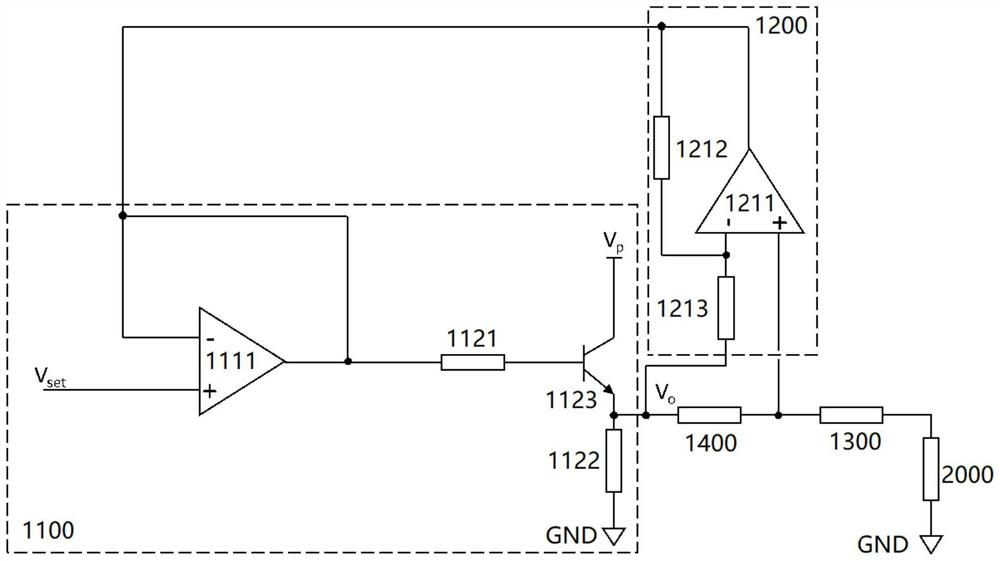
The invention provides a cable voltage drop compensation circuit and an ultrasonic imaging system. The cable voltage drop compensation circuit comprises a voltage stabilization module, a sampling conversion module, a cable which is used for connecting a load, and a sampling resistor which is connected between the voltage stabilization module and the cable. The voltage stabilization module is configured to output a current and a first voltage to the sampling resistor. The sampling conversion module is configured to collect a second voltage generated at the two ends of the sampling resistor when the current passes through the sampling resistor, convert the second voltage into a third voltage according to a set rule, and output the third voltage to the voltage stabilization module. The voltage stabilization module is configured to adjust the first voltage according to the third voltage so as to compensate the voltage drop generated by the current on the cable.

Description

technical field [0001] The present invention relates to the technical field of circuit design, and more specifically, the present invention relates to a cable voltage drop compensation circuit and an ultrasonic imaging system. Background technique [0002] Existing ultrasound imaging systems generally include ultrasound imaging equipment, cables, and ultrasound probes. The ultrasound imaging device can be connected to the ultrasound probe through a cable, and transmits electrical signals to the ultrasound probe through the cable. [0003] With the increase of the number of transducer elements in the ultrasonic probe, in order not to increase the number of cores inside the cable, more and more electronic components are integrated in the ultrasonic probe to control and select different transducer elements. . Therefore, ultrasound imaging equipment needs to provide sufficient voltage and current to the electronic components inside the ultrasound probe. [0004] Since the pow...

Claims


Application Information

Patent Timeline
Patent Type & Authority Applications(China)
IPC IPC(8): G05F1/56
CPCG05F1/56
Inventor 吴楠安普岩
Owner 逸超科技(武汉)有限公司
Learn More