
Imaging method and device based on ultrasonic Lamb wave defect detection

A technology of ultrasonic lamb wave and defect detection, which is applied in the direction of analyzing solids using sound waves/ultrasonic waves/infrasonic waves, and can solve the problems of inability to form high-resolution detection images, failure to form high-resolution detection images, and ignoring useful information, etc.

Active Publication Date: 2021-11-23
INST OF ACOUSTICS CHINESE ACAD OF SCI
View PDF7 Cites 2 Cited by
  • Summary
  • Abstract
  • Description
  • Claims
  • Application Information

AI Technical Summary

Problems solved by technology

However, due to the influence of the dispersion and multi-mode characteristics of the Lamb wave, the influence of these characteristics is usually avoided when the Lamb wave is used for detection, so it is impossible to form a high-resolution detection image
[0003] Usually, when Lamb wave is used for defect detection, a single mode Lamb wave is selectively excited for detection, but when the wave propagates to the defect position and interacts with the defect, the dispersion and multi-mode phenomena cannot be avoided
Conventional imaging algorithms usually only extract the Lamb wave signal of a certain mode for imaging, while ignoring the useful information contained in the dispersed waves of multiple modes, so it is impossible to form a high-resolution detection image

Method used


Image

  • Imaging method and device based on ultrasonic Lamb wave defect detection
  • Imaging method and device based on ultrasonic Lamb wave defect detection
  • Imaging method and device based on ultrasonic Lamb wave defect detection

Examples


Embodiment Construction

[0045] The technical solutions of the present application will be described in further detail below with reference to the drawings and embodiments.

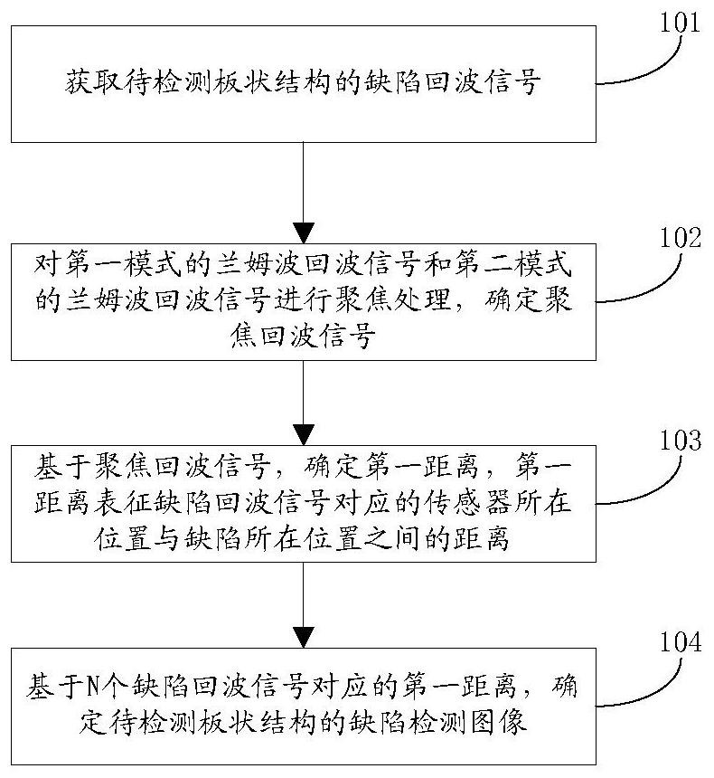
[0046] figure 1 The flow chart of the imaging method based on ultrasonic Lamb wave defect detection provided by the embodiment of this application. Such as figure 1 As shown, the method includes step S101-step S104.

[0047] In step S101, the defect echo signal of the plate structure to be detected is acquired.

[0048] Exemplarily, the probe is fixed on the plate-like structure to be detected, N sensors are arranged in the region of interest (that is, the region to be detected) of the plate-like structure to be detected, and ultrasonic Lamb waves are generated by excitation of the probe. When the plate-like structure to be detected When there is a defect in the plate-shaped structure, N sensors receive defect echo signals, and the defect echo signals of the plate-shaped structure to be detected are obtained by acquiring the d...


PUM


Abstract

The invention relates to an imaging method based on ultrasonic Lamb wave defect detection, the method comprises the following steps: acquiring defect echo signals of a to-be-detected plate-shaped structure, the defect echo signals at least comprising a first mode Lamb wave echo signal and a second mode Lamb wave echo signal; performing focusing processing on the Lamb wave echo signal of the first mode and the Lamb wave echo signal of the second mode, and determining a focused echo signal; based on the focusing echo signal, determining a first distance, wherein the first distance represents the distance between the position of the sensor corresponding to the defect echo signal and the position of the defect; and determining a defect detection image of the to-be-detected plate-shaped structure based on the first distance corresponding to the N defect echo signals. According to the imaging method based on ultrasonic Lamb wave defect detection, high-precision imaging of defects in the two-dimensional plate-shaped structure can be achieved.

Description

technical field [0001] This application relates to the technical field of non-destructive testing, in particular to an imaging method and device based on ultrasonic Lamb wave defect detection. Background technique [0002] Ultrasonic Lamb wave (Lamb wave) detection technology has attracted much attention because of its large detection range and high detection efficiency. It is a fast and effective nondestructive detection method suitable for long-distance and large-area structures. This technology has been widely used in the detection and evaluation of engineering structures. However, due to the influence of the dispersion and multi-mode characteristics of the Lamb wave, the influence of these characteristics is usually avoided when the Lamb wave is used for detection, so it is impossible to form a high-resolution detection image. [0003] Usually, when Lamb wave is used for defect detection, a single mode Lamb wave is selectively excited for detection, but when the wave pr...

Claims


Application Information

Patent Timeline
Patent Type & Authority Applications(China)
IPC IPC(8): G01N29/04G01N29/06
CPCG01N29/041G01N29/069G01N2291/0289
Inventor 阎守国黄娟阚婷婷张碧星
Owner INST OF ACOUSTICS CHINESE ACAD OF SCI
Learn More