
Controllable two-way grout stopping device for sleeve valve pipe

A sleeve valve tube and slurry stop technology is applied in the field of controllable two-way slurry stop devices, which can solve the problems of high grouting pressure, failure to reset the slurry stop plug, and the slurry stop plug stuck in the tube, and achieves the effect of improving stability.

Active Publication Date: 2021-11-23
THE THIRD ENG CO LTD OF CHINA RAILWAY SEVENTH GRP +3
View PDF5 Cites 0 Cited by
  • Summary
  • Abstract
  • Description
  • Claims
  • Application Information

AI Technical Summary

Problems solved by technology

However, the polyurethane (rubber) sealing ring grout stopper has certain disadvantages. When grouting in clay or medium-fine sand and other formations, the grouting pressure is often high. When the grouting pressure is greater than 2MPa, the cup will not The type grout stopper is easy to turn over or be pulled off, which leads to the series connection of the cups, the grout stopper cannot be reset, and the grout stopper jams the tube, and it is very difficult to lift the tube; for some deep hole grouting, because the grouting device is lowered deeply, Under the action of the grouting pressure, a "syringe" effect is formed, and it is also very difficult to lift the tube; at this time, if a large lifting force is used, the threaded connection parts of the flower tube will be disconnected, and eventually the flower tube and the grouting tube will be broken. scrapped

Method used


Image

  • Controllable two-way grout stopping device for sleeve valve pipe
  • Controllable two-way grout stopping device for sleeve valve pipe
  • Controllable two-way grout stopping device for sleeve valve pipe

Examples


Embodiment 1

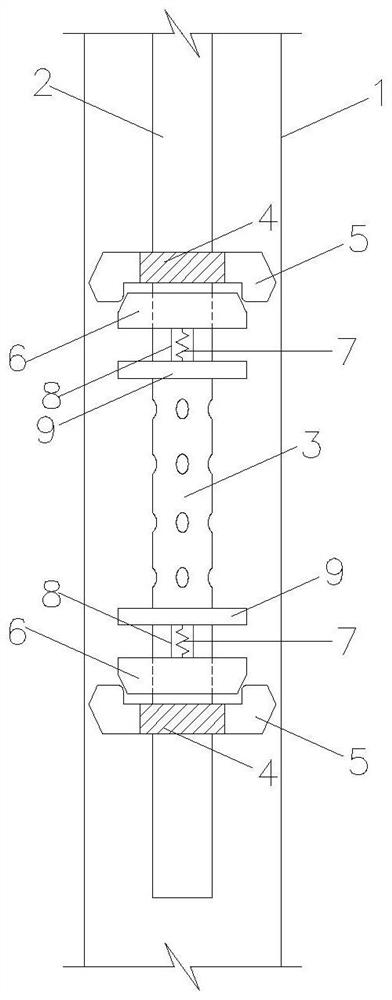
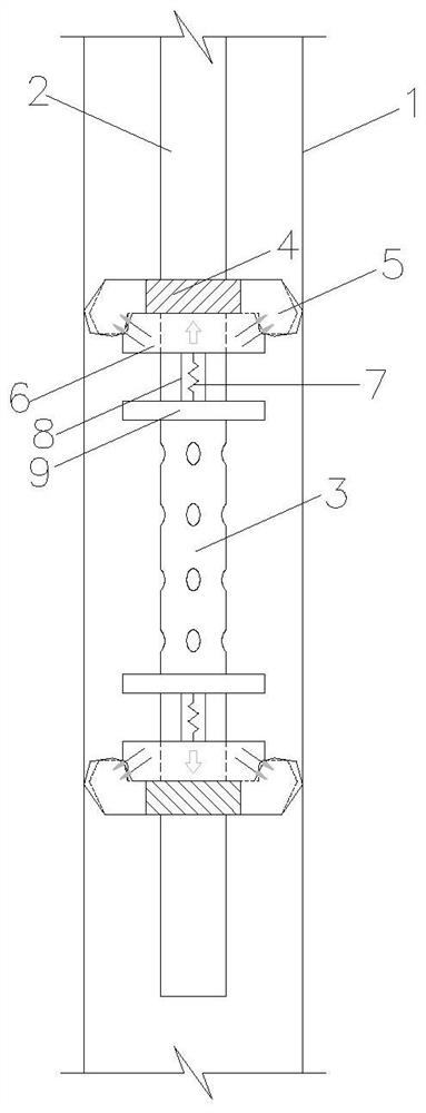
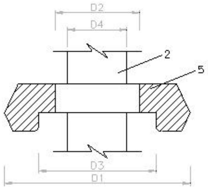
[0026] This embodiment provides a controllable two-way slurry stop device for the sleeve valve tube, such as Figure 1-7 As shown, the metal stopper 9, the return spring group 7, the round table metal slider 6, the polyurethane grout stopper, and the ring-shaped suction cup electromagnet 4 are arranged sequentially outward from both sides of the grouting steel flower tube 3. The suction cup electromagnet 4 is connected with the outside 24V DC power supply and the electromagnet switch through the lead wire; in the working state, the ring-shaped suction cup electromagnet is connected with the corresponding round table metal slider, and one end of the round table metal slider is pushed into the polyurethane stop In the groove of the grout plug, the polyurethane grout stopper is in close contact with the wall of the sleeve valve pipe, and the other end of the metal slider of the round table is connected with the limit stopper through the return spring group, and the limit stopper i...


PUM


Abstract

The invention discloses a controllable two-way grout stopping device for a sleeve valve pipe. The controllable two-way grout stopping device comprises a circular truncated cone metal sliding block, a polyurethane grout stopping plug, an annular sucker electromagnet, a limiting stop block and a reset spring group, when the annular sucker electromagnet is electrified, under the action of electromagnetic force, the circular truncated cone metal sliding block is attracted to the annular sucker electromagnet, therefore, the polyurethane grout stopping plug is extruded to force the cantilever to deform, the sleeve valve pipe is wedged, and meanwhile the reset spring set is lengthened, when the annular suction cup electromagnet is powered off, the circular truncated cone metal sliding block rebounds, meanwhile, the reset spring set recovers deformation and assists the circular truncated cone metal sliding block to be disengaged from the polyurethane grout stopping plug, and therefore the grout stopping plug recovers deformation and is disengaged from the pipe wall of the sleeve valve pipe. According to the controllable two-way grout stopping device, opening and closing of the grouting stopping device can be manually controlled, so that it is guaranteed that the grouting device is smoothly lowered and lifted, and the grouting efficiency and the stability of the grouting effect are improved.

Description

technical field [0001] The invention belongs to the technical field of civil engineering, and in particular relates to a controllable two-way slurry stop device for sleeve valve pipes. Background technique [0002] The sleeve valve pipe grouting method is a grouting method developed and researched by the French Soletanche Basic Engineering Company. It is internationally recognized that this method is relatively reliable. At the end of the 1980s in China, it began to be used in the infiltration grouting of sandy gravel layer and sand pebble layer, soft soil splitting grouting and deep soil splitting grouting. In view of the good reinforcement, anti-seepage and plugging effects of sleeve valve pipe grouting, it is widely used in foundation pit curtain, soft soil roadbed reinforcement and other projects. [0003] The basic process and principle of sleeve valve pipe grouting are as follows: the grout enters the grouting pipe through the connecting pipe after being pressurized b...

Claims


Application Information

Patent Timeline
Patent Type & Authority Applications(China)
IPC IPC(8): E02D15/02E02D3/12
CPCE02D15/02E02D3/12
Inventor 谢军张志军潘兴良余勇朝王海江李建雨余海波章新生赵晓明张红星王建新李端书刘永祥徐恢荣王峥峥
Owner THE THIRD ENG CO LTD OF CHINA RAILWAY SEVENTH GRP
Learn More