Safety elevator landing door

A safety elevator and floor door technology, which is applied to elevators, transportation and packaging in buildings, etc., can solve the problems of ground impact damage, damage to the ground floor of the building, and affect the stability of the building, so as to strengthen the impact ability and improve the protection ability. , to avoid the effect of firmness

Pending Publication Date: 2021-11-19
徐浩波
View PDF14 Cites 0 Cited by
  • Summary
  • Abstract
  • Description
  • Claims
  • Application Information

AI Technical Summary

Problems solved by technology

[0002] The elevator landing door is the door that people see outside the elevator, also called hall door; the opening and closing of the landing door is realized by the door opening blade installed on the car door; after the landing door is closed, the mechanical lock hook of the door lock At the same time, the electrical interlocking contact between the landing door and the car door is closed, and the elevator control circuit is connected, and the elevator can start running at this time; the elevator landing door has a fireproof function in the building and is used to divide the fire compartment; It will affect the explosion. The shock wave of the explosion will impact the elevator landing door. When the elevator landing door is hit, it is easy to be smashed open. Therefore, the shock wave and flame will impact into the interior of the elevator shaft, destroying the bottom floor of the building along the elevator shaft, and affecting the overall stability of the building. At the same time, the elevator car inside the elevator shaft will be affected by the impact, and in severe cases, it will fall and cause impact damage to the ground
[0003] For example, a Chinese patent of CN201811515926.9 discloses an anti-collision elevator landing door. The technical solution includes installing steel plates, and the outer walls of the four corners of the front of the installing steel plate have first mounting holes, and the inside of the four first mounting holes are all provided with There are fixing bolts, the front outer wall of the installation steel plate is fixed with electric slide rails by bolts, and the front outer walls at both ends of the electric slide rail are fixed with buffer balls by bolts, and the inner wall of the electric slide rail is slidingly connected with two sliders, and the two The front outer walls of each slider are fixed with fixed blocks by bolts, and the outer walls on both sides of the two fixed blocks are fixed with two return springs by bolts, and the outer walls on the same side of every two return springs are fixed with the same stopper by bolts. The outer walls of the four baffle plates away from the return spring are all provided with rubber protrusions; this technical solution can reduce the shaking generated when the two elevator landing doors are attached to each other, improve the stability of the elevator landing doors, and promote The stable effect of opening and closing of the left and right elevator landing doors; but this technical solution also has disadvantages. The position of installing the steel plate is located above the door body, and the impact force received is not as large as the impact received by the door body, which cannot effectively solve the problem that the door body will open when it is impacted. This situation can not effectively prevent the fire and the shock wave generated by the fire, so that the safety of people's property cannot be effectively protected, thus causing the limitations of the program

Method used


Image

  • Safety elevator landing door
  • Safety elevator landing door
  • Safety elevator landing door

Examples


Embodiment approach

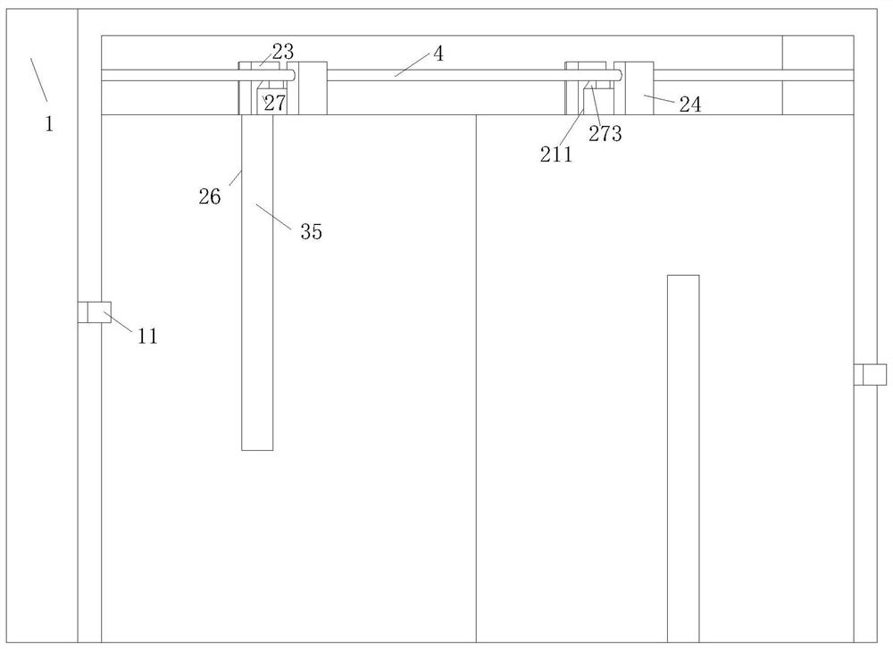
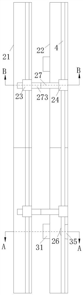
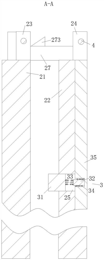
[0040] As an embodiment of the present invention, the pop-up interception module 3 includes a No. 1 displacement block 31, a No. 2 displacement block 32, a No. 1 spring 33, a torsion spring 34 and a rotating rod 35; the No. 1 displacement block 31 is slidably connected Inside No. 1 groove 25, No. 1 displacement block 31 stretches out No. 1 groove 25 near one end of No. 1 door body 21, No. 1 displacement block 31 and No. 2 displacement block 32 are connected by No. 1 spring 33; The end face of the No. 1 door body 22 away from the No. 1 door body 21 is provided with a No. 2 groove 26; the number of the No. 2 groove 26 is two, and the No. 2 groove 26 communicates with the No. 1 groove 25; the No. 2 groove The inside of the groove 26 is provided with a rotating rod 35; the rotating rod 35 is connected to the No. 2 displacement block 32 through the rotation of the torsion spring 34, and the rotating rod 35 is stuck in the No. 2 groove 26 in the initial state;

[0041] During work, ...


PUM


Abstract

The invention belongs to the technical field of elevator landing doors, and particularly relates to a safety elevator landing door. The safety elevator landing door comprises a door frame, a door body, a sliding rod and a controller, a first door body and a second door body are installed on the door frame in parallel, the end face, close to the door frame, of the first door body is fixedly connected with a first sliding block, a second sliding block is fixedly connected to the end face, close to the door frame, of the upper portion of the second door body, the first sliding block and the second sliding block are both connected with the sliding rod in a sliding mode, the end face, close to the first door body, of the second door body is provided with a first groove, and a pop-up intercepting module is arranged in the interior of the first groove. According to the safety elevator landing door, the door body is arranged to be of a two-layer structure, in cooperation with the facts that the first groove is formed in the interior of the second door body and the pop-up intercepting device is arranged in the interior of the first groove, when the door body is impacted, the pop-up intercepting mechanism can prevent the door body from being knocked open, then an elevator shaft is protected against damage, the impact resistance of the elevator landing door is enhanced when a fire disaster happens, and the safety of a building body can be guaranteed when the fire disaster happens.

Description

technical field [0001] The invention belongs to the technical field of elevator landing doors, in particular to a safe elevator landing door. Background technique [0002] The elevator landing door is the door that people see outside the elevator, also called hall door; the opening and closing of the landing door is realized by the door opening blade installed on the car door; after the landing door is closed, the mechanical lock hook of the door lock At the same time, the electrical interlocking contact between the landing door and the car door is closed, and the elevator control circuit is connected, and the elevator can start running at this time; the elevator landing door has a fireproof function in the building and is used to divide the fire compartment; It will affect the explosion. The shock wave of the explosion will impact the elevator landing door. When the elevator landing door is hit, it is easy to be smashed open. Therefore, the shock wave and flame will impact ...

Claims


Application Information

Patent Timeline
Patent Type & Authority Applications(China)
IPC IPC(8): B66B13/30
CPCB66B13/30
Inventor 徐浩波张秀平何水枝
Owner 徐浩波
Why Eureka
Try Eureka