
Method for manufacturing air bag, air bag, and seat device for vehicle

A manufacturing method and air bag technology, which can be applied to vehicle seats, special positions of vehicles, vehicle parts, etc., can solve problems such as fractures in peripheral parts, and achieve the effect of improving durability.

Pending Publication Date: 2021-11-19
AISIN CORP
View PDF2 Cites 0 Cited by
  • Summary
  • Abstract
  • Description
  • Claims
  • Application Information

AI Technical Summary

Problems solved by technology

[0005] However, in the above-mentioned air bag, when the bag is filled with air and the bag is expanded, stress tends to concentrate on the portion where the sheets are joined together, that is, the peripheral portion of the bag.
Therefore, in the case where an excessive load is applied to the bag portion, there is a possibility that a rupture may be formed at the peripheral edge portion, so there is still room for improvement in this proposal.

Method used


Image

  • Method for manufacturing air bag, air bag, and seat device for vehicle
  • Method for manufacturing air bag, air bag, and seat device for vehicle
  • Method for manufacturing air bag, air bag, and seat device for vehicle

Examples


Embodiment Construction

[0048] Hereinafter, an embodiment of an air bag and a vehicle seat device will be described with reference to the drawings.

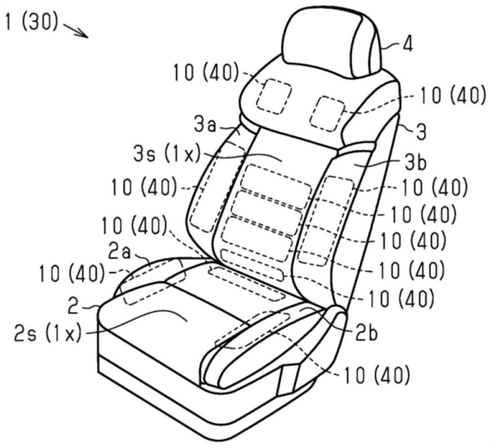
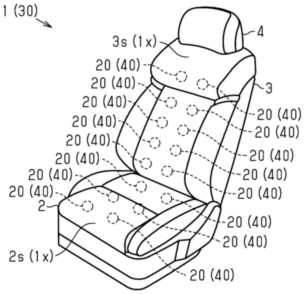
[0049] Such as figure 1 and figure 2 As shown, a vehicle seat 1 includes a seat cushion 2 and a seat back 3 provided at a rear end portion of the seat cushion 2 . Furthermore, a headrest 4 is provided on the upper end of the seat back 3 .

[0050] In addition, in the seat 1 of the present embodiment, the seat back 3 has a shape in which both side portions 3a, 3b are respectively swollen toward the front. Furthermore, the seat cushion 2 also has a shape in which both side parts 2a and 2b bulge upward, respectively. Then, the seat 1 of the present embodiment thereby becomes capable of securing a good sitting posture of the occupant and maintaining the sitting posture.

[0051] In addition, the seat 1 is provided with a plurality of air bags 10 that expand and contract inside the seat cushion 2 and the seat back 3 to change the supporting shape of the...


PUM


Abstract

Provided is a method for manufacturing an air bag having excellent durability. For an air bag (40), a welding die (60) is pressed against two sheets (41, 42) arranged in an overlapping manner from the overlapping direction of the sheets (41, 42), thereby forming a bag part (45) surrounded by a welding part (50) extending in a ring shape. Furthermore, the deposition die (60) is pressed against the outer surface (42s) of the sheet (42), thereby forming a deposition section (50) of the two sheets (41, 42), the deposition section (50) having a deposition bead section (80) between the two sheets (41, 42), the deposition bead section (80) protruding toward the inside of the pocket section (45). Furthermore, on the pressing surface (70) of the deposition die (60) with respect to the sheet (42), an inclined surface section (75) facing the overlapping direction of the sheets (41, 42) and the direction of the inside of the pocket section (45) is provided on the outer side of the pocket section (45) with respect to the formation position of the deposition bead section (80).

Description

technical field [0001] The present invention relates to a method for manufacturing an air bag, an air bag, and a vehicle seat device. Background technique [0002] Conventionally, for example, as shown in Patent Document 1, there is a vehicle seat device configured to expand and contract an air bag provided on the inner side of the seat skin to obtain the desired airflow of a passenger seated in the seat. relaxing effect. In addition, among the air bags used in such vehicle seats, for example, as disclosed in Patent Document 2, there is an air bag having a bag portion constituted by bonding two sheets. Furthermore, the use of such an air bag enables simplification of the structure. [0003] Patent Document 1: Japanese Patent No. 4305663 [0004] Patent Document 2: Japanese Patent Laid-Open No. 2015-96403 [0005] However, in the above-mentioned air bag, when the bag is filled with air and the bag is expanded, stress tends to concentrate on the portion where the sheets ar...

Claims


Application Information

Patent Timeline
IPC IPC(8): B29C65/18B60N2/90B29L22/02
CPCB29C65/18B60N2/976B29L2022/027B60N2/914B29C66/1122B29C66/43B29C66/346B29C66/73921B29C66/81425B29C66/81427B29C66/81422B29C66/81423B29C66/81431B29C66/83221B29C66/8322B29C66/242B29C66/71B29C65/04B29K2027/06B29C66/436B29L2031/58B29L2031/443
Inventor 榑松靖人酒井诚水野量介增田贤志关诚雄长谷川正明山本刚志神原朋子
Owner AISIN CORP
Learn More