Lifting device for preventing concrete from dripping

A concrete and hoist technology, applied in the direction of supply devices, manufacturing tools, etc., can solve problems such as eye damage, hoisting device jamming, and easy sputtering

Active Publication Date: 2021-11-19
CHINA MCC17 GRP
View PDF7 Cites 0 Cited by
  • Summary
  • Abstract
  • Description
  • Claims
  • Application Information

AI Technical Summary

Problems solved by technology

[0005] Aiming at the deficiencies of the prior art, the present invention provides a lifting device for preventing concrete dripping, which has a wide application range and high safety, and the concrete used in the market When the lifting equipment is being shipped, due to the internal rotation of the concrete mixer, the falling concrete is easily splashed at a certain speed and sticks to the truck, resulting in the phenomenon of concrete dripping during transportation, and the dripping of concrete will It will cause damage to the eyes of the staff. Not only that, if the concrete is not cleaned up in time after dripping, it will solidify. The solidified concrete is difficult to remove and may cause the lifting device to get stuck, causing the machine to fail to operate normally and delay the construction period.

Method used


Image

  • Lifting device for preventing concrete from dripping
  • Lifting device for preventing concrete from dripping
  • Lifting device for preventing concrete from dripping

Examples


Embodiment 1

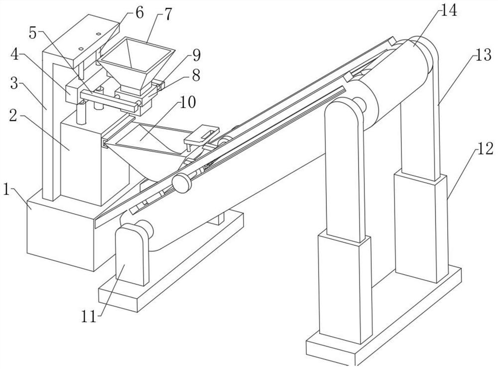
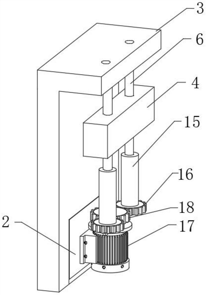
[0028]A lifting device for preventing concrete dripping, comprising a fixed base 1, characterized in that: the upper surface of the fixed base 1 is fixedly connected with a power bin 2, and one side of the outer surface of the power bin 2 is provided with a card slot block, and the outer surface of the power bin 2 The other side of the surface is fixedly connected with a fixed plate 3, the upper surface of the power bin 2 is provided with a lifting mechanism, one side of the outer surface of the fixed base 1 is fixedly connected with a hoist 14, and one end of the hoist is fixedly connected with a front support frame 11, The other end of the hoist 14 is fixedly connected with a lifting column 13, the lower surface of the lifting column 13 is fixedly connected with a rear support frame 12, and the upper surface of the hoist 14 is provided with a transport vehicle 10, and one end of the transport vehicle 10 is engaged with the movable block of the slot block. Then, the lifting me...

Embodiment 2

[0030] Embodiment 2: the difference based on Embodiment 1 is;

[0031] The inside of the hoist 14 is fixedly equipped with a motor 28, and one end of the motor 28 is fixedly connected with a starting shaft, and the outer surface of the starting shaft is fixedly connected with two winding wheels 29, and the inside of the winding wheel 29 is fixedly connected with a connecting belt 31, and the connecting belt 31 The outer surface of the middle part is movably connected with a sleeve wheel 32, and the upper surface of the hoist 14 is fixedly connected with a splint 30. The middle part of the splint 30 is provided with two strip holes, and the connecting belt 31 runs through the strip hole movably. The other end is fixedly connected with a socket wheel 32, the inner surface of the socket wheel 32 is movably socketed with a penetrating column 33, the outer surface of the penetrating column 33 is provided with a fixed shell 35, and the two sides of the fixed shell 35 are fixedly conn...

Embodiment 3

[0033] Embodiment 3: the difference based on embodiment 1 is;

[0034] The outer surface of movable shaft 19 is movably connected with bearing 26, and the outer surface of bearing 26 is fixedly connected with movable wheel 27, and the front surface of movable wheel 27 is fixedly connected with clamp post 36, and the other end of clamp post 36 is fixedly connected with limit wheel 37, The upper surface of the transport vehicle 10 is fixedly connected with a pull plate 25, the lower surface of the transport vehicle 10 is fixedly connected with a connecting column 23, the lower surface of the connecting column 23 is fixedly connected with a connecting shaft 24, and the two sides of the connecting shaft 24 are fixedly connected with rolling wheels. , the outer surface of movable shaft 19 is fixedly connected with connecting rod 20, and one end of connecting rod 20 is fixedly connected with fixed ring 21, and one side of transport vehicle 10 outer surface offers movable groove, and ...


PUM


Abstract

The invention relates to the technical field of concrete lifting, and discloses a lifting device for preventing concrete from dripping. The lifting device comprises a fixed base, a power bin is fixedly connected to the upper surface of the fixed base, a clamping groove block is arranged on one side of the outer surface of the power bin, a fixed plate is fixedly connected to the other side of the outer surface of the power bin, and a lifting mechanism is arranged on the upper surface of the power bin. The problems that when concrete lifting equipment used in the market carries out loading and transporting, due to the fact that the interior of a concrete mixer rotates, falling-out concrete is likely to sputter and adhere to a loading and transporting vehicle at a certain speed, the phenomenon that the concrete drips in the transporting process is caused, eyes of workers are damaged due to dripping of concrete, the dripped concrete is solidified if not cleared away in time, the solidified concrete is difficult to remove, a lifting device may be jammed, a machine cannot operate normally, and the construction period is delayed are solved.

Description

technical field [0001] The invention relates to the technical field of concrete lifting, in particular to a lifting device for preventing concrete from dripping. Background technique [0002] Elevator (well elevating conveyor / Elevator) is a large-scale mechanical equipment that is transported by changing potential energy, such as mine elevators, dam crossing elevators, etc. Broadly speaking, elevators, cranes, hoists, stabilizers, cranes, hoists, etc. can all be called hoists. Hoists generally refer to large-scale mechanical equipment with high power and strong lifting capacity. The flexible steel wire rope and the transported goods move up and down to complete the transportation process. The steel wire rope is an indispensable and important part of the hoisting machinery. The main varieties are phosphating coated steel wire rope, galvanized steel wire rope, stainless steel wire rope, smooth steel wire rope and so on. [0003] At present, when the concrete lifting equipment...

Claims


Application Information

Patent Timeline
IPC IPC(8): B28B13/02
CPCB28B13/02
Inventor 崔晓辉杨晓红马龙张志全程然
Owner CHINA MCC17 GRP
Why Eureka
Try Eureka