Novel high-performance welding robot based on three-dimensional form
A welding robot, high-performance technology, applied in welding equipment, laser welding equipment, metal processing equipment, etc., to reduce the possibility of eye damage and the possible effect of reducing the possibility of looking directly at the arc light
- Summary
- Abstract
- Description
- Claims
- Application Information
AI Technical Summary
Problems solved by technology
Method used
Image
Examples
Embodiment 1
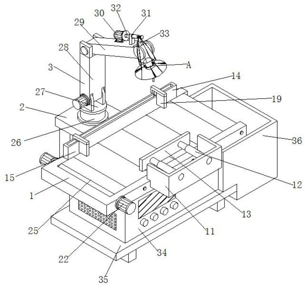
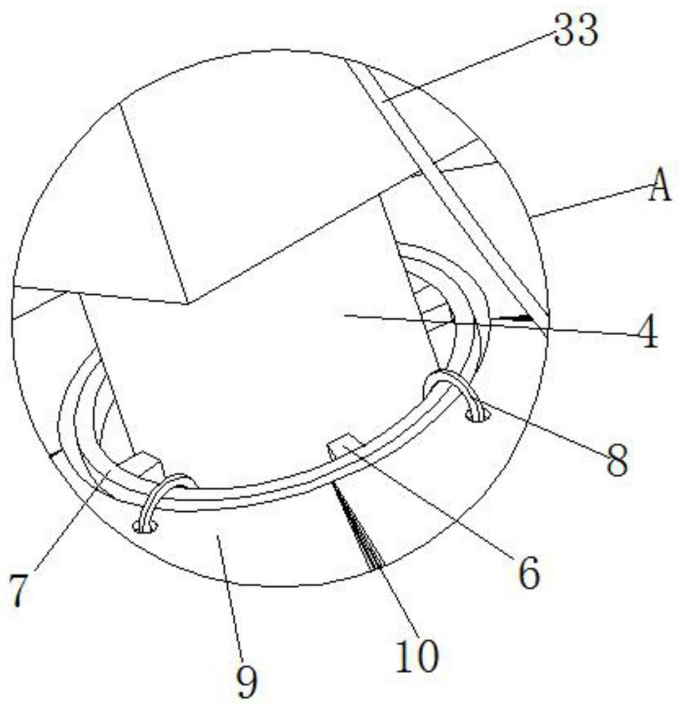
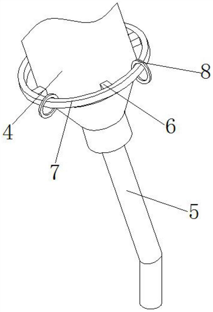
[0041] Such as figure 1 , figure 2 with image 3 As shown, a new high-performance welding robot based on a three-dimensional form includes a work frame 1, a storage board 2, a machine body 3 and a high pressure head 4, a storage board 2 is installed on the back of the work frame 1, and the bottom of the storage board 2 A column is installed, a machine main body 3 is installed on the top of the storage board 2, and a high pressure head 4 is installed at the tail end of the machine main body 3;
[0042] Concrete, working frame 1 can be convenient to the installation of the conveying structure that rotating motor 22, turning roller 23, guide roller 24 and conveyor belt 25 are combined, simultaneously the top of working frame 1 and the top of conveying belt 25 are on the same level, between the two There are no ups and downs between them, which can ensure the stability of the welded product. The storage board 2 is used to install the machine body 3. The machine body 3 passes th...
Embodiment 2
[0048] Such as Figure 4 , Figure 5 with Image 6 As shown, the front of the work frame 1 is equipped with a fixed frame 11, and the front of the fixed frame 11 is equipped with two groups of electric telescopic rods 12 arranged side by side, and the back side of the electric telescopic rods 12 runs through the inside of the fixed frame 11, and the electric telescopic rods 12 A limiting plate 13 is installed on the back, and the limiting plate 13 is located above the working frame 1 .
[0049] Specifically, the fixed frame 11 is used to install the electric telescopic rod 12, and there is a certain distance between the front plate of the fixed frame 11 and the working frame 1. When the electric telescopic rod 12 is not activated, the bottom of the limit plate 13 installed at one end It fits with the top of the working frame 1 near the side where the fixed frame 11 is located, and then reserves enough space between the limiting plate 13 and the strip block 14, so that it is ...
Embodiment 3
[0053] Such as Figure 7 with Figure 8 As shown, the front and the back of the working frame 1 are equipped with a rotating motor 22, and the output end of the rotating motor 22 is equipped with a rotating shaft, and the front of one group of rotating shafts is equipped with a rotating roller 23, and the front of the rotating roller 23 is connected with another group of rotating shafts. The back side of the work frame 1 is uniformly equipped with multiple groups of guide rollers 24 arranged side by side, and the back side of the guide rollers 24 runs through the inside of the work frame 1, and the multiple groups of guide rollers 24 are all located on one side of the rotating roller 23. A conveyor belt 25 is installed on the outer surface of the roller 23 , and the inner wall of the conveyor belt 25 is attached to the outer wall of the guide roller 24 .
[0054] Specifically, after the rotating motor 22 is started, the rotating shaft installed at its output end can rotate ac...
PUM
 Abstract
Description
Claims
Application Information
 - R&D
- Intellectual Property
- Life Sciences
- Materials
- Tech Scout
- Unparalleled Data Quality
- Higher Quality Content
- 60% Fewer Hallucinations
Browse by: Latest US Patents, China's latest patents, Technical Efficacy Thesaurus, Application Domain, Technology Topic, Popular Technical Reports.
© 2025 PatSnap. All rights reserved.Legal|Privacy policy|Modern Slavery Act Transparency Statement|Sitemap|About US| Contact US: help@patsnap.com


