
Continuous optical change device for lens motor

A technology of motors and lenses, applied in the field of continuous optical variable devices, can solve the problems of driving force decline and other problems, and achieve the effect of meeting the requirements of optical zoom and focusing

Pending Publication Date: 2021-11-16
辽宁中蓝光电科技有限公司
View PDF0 Cites 0 Cited by
  • Summary
  • Abstract
  • Description
  • Claims
  • Application Information

AI Technical Summary

Problems solved by technology

[0003] In view of the above-mentioned shortcomings and deficiencies of the prior art, the present invention provides a continuous optical variable device for lens motors, which solves the technical problem that the long-stroke movement of the lens group required for optical zoom results in a decrease in driving force

Method used


Image

  • Continuous optical change device for lens motor
  • Continuous optical change device for lens motor
  • Continuous optical change device for lens motor

Examples


Embodiment 1

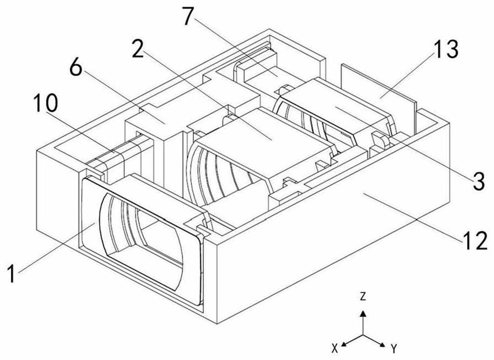
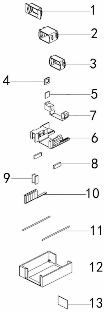
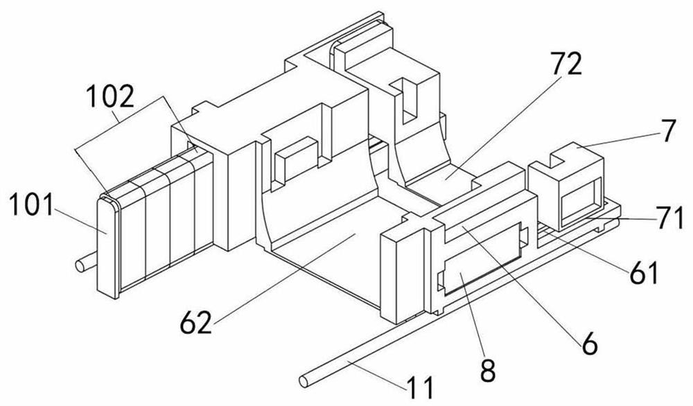
[0025] refer to figure 1 and figure 2 , the invention provides a continuous optical variable device for a lens motor. The device includes: an optical fixed component 1 , a first optical movable component 2 , a second optical movable component 3 , a first carrier 6 , a second carrier 7 , and a base 12 . Wherein, the optical fixing assembly 1 is disposed on one side of the base 12 , and the image sensor 13 is disposed on the other side of the base 12 . The first carrier 6 is arranged on the base 12 for carrying the first optical active assembly 2 . The second carrier 7 is arranged at one end of the first carrier 6 for carrying the second optical active assembly 3 . The first carrier 6 is connected to the first drive mechanism, and the first drive mechanism drives the first carrier 6 to move in the X-axis direction, thereby driving the first optical movable assembly 2 and the second optical movable assembly 3 relative to the optical fixed assembly 1 Move synchronously in the...


PUM


Abstract

The invention relates to the technical field of optical lens zooming, in particular to a continuous optical variable device for a lens motor, which comprises: a base; an optical fixing assembly and an image sensor which are arranged on the two sides of the base; a first carrier which is arranged on the base and is used for bearing a first optical movable component; and a second carrier which is arranged on one side of the first carrier and is used for bearing a second optical movable component. The first carrier is connected with the first driving mechanism, the first carrier is driven by the first driving mechanism to move in the first axial direction, and then the first optical movable assembly and the second optical movable assembly are driven to synchronously move in the first axial direction relative to the optical fixed assembly; and the second carrier is connected with the second driving mechanism, and the second driving mechanism drives the second carrier to move in the first axial direction so as to drive the second optical movable assembly to move in the first axial direction relative to the first optical movable assembly and the optical fixed assembly. According to the invention, long-stroke movement of the lens group can be realized, and optical zooming and focusing requirements are met.

Description

technical field [0001] The invention relates to the technical field of optical lens zooming, in particular to a continuous optical variable device for a lens motor. Background technique [0002] At present, the lens used on the mobile phone gradually increases the optical zoom technology, and then realizes the function of the telephoto lens. Among them, the telephoto lens is longer than the traditional wide-angle lens. If the current direct exposure method of the mobile phone lens is used, the mobile phone lens will protrude a lot from the surface of the casing, resulting in inconsistent appearance and easy to cause damage to the camera. Contents of the invention [0003] In view of the above-mentioned shortcomings and deficiencies of the prior art, the present invention provides a continuous optical variable device for a lens motor, which solves the technical problem that the long-stroke movement of the lens group required for optical zoom leads to a decrease in driving f...

Claims


Application Information

Patent Timeline
Patent Type & Authority Applications(China)
IPC IPC(8): G02B7/10G03B13/34G03B30/00H02K5/00H02K41/035
CPCG02B7/10G03B13/34G03B30/00H02K5/00H02K41/0354H02K41/0356
Inventor 游证凯宋秉儒许乃文吴发权
Owner 辽宁中蓝光电科技有限公司
Learn More