Adjustable fixing support for installation of instruments and meters
A technology for fixing brackets and instruments, applied in the field of brackets, can solve the problems of inconvenient instrument installation, shaking during instrument clamping, and inability to clamp and buffer instruments, so as to achieve beautiful placement effect, avoid collision damage, and ensure neat placement. Effect
- Summary
- Abstract
- Description
- Claims
- Application Information
AI Technical Summary
Problems solved by technology
Method used
Image
Examples
Embodiment 1
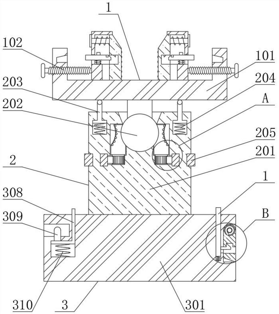
[0026] See Figure 1-6 The present invention provides a technical solution:
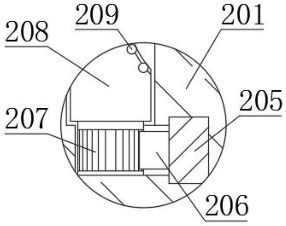
[0027] An instrumentation mounting of adjustable fixing bracket, including clamping fixing mechanism 1, angle adjustment mechanism 2, and base connection mechanism 3, the top end of the base connection mechanism 3 is provided with an angle adjustment mechanism 2, and the top end of the angle adjustment mechanism 2 is provided The clamping mechanism 1, the clamping fixing mechanism 1 includes a U-shaped placement plate 101, a screw 102, a clamping seat 103, a slide plate 104, a positioning rod 105, a first spring 106, a triangular block 107, a central rod 108, a slot rod? 109 and the second spring 110, the left end of the U-type place plate 101 is threaded with the inside of the rear end, and the right end of the screw 102 located on the left side is rotated to the left side of the screw 102 on the right side. The seat 103, which is rotated by the screw 102, can be slid on the top end surface of the U-shap...
Embodiment 2
[0031] See Figure 1-6 The present invention provides a technical solution:
[0032] An instrumentation mounting with an adjustable fixed bracket, in Example 2, in Example 1, in the present invention, in the present invention, the difference is in the workflow.
[0033] Workflow: When adjusting the placement angle of the instrumentation, the rotary disc 205 is first turned to rotate the turntable disk 205 with the gear post 207 to rotate, the gear post 207 is rotated after rotation. The friction column 208 is rotated until the placement tank on the inside of the friction column 208 is disposed on the outer end surface of the ball head 202, and the sliding bead 209 is rotated to the ball head 202, and the ball 202 can be rotated by the sliding bead 202, thereby achieving the U-shaped When the angle of the placement plate 101 is arbitrarily adjusted, after the adjustment is completed, the rotary disk 205 is rotated, so that the turntable disk 205 drives the gear post 207 in reverse r...
PUM
 Abstract
Description
Claims
Application Information
 - R&D
- Intellectual Property
- Life Sciences
- Materials
- Tech Scout
- Unparalleled Data Quality
- Higher Quality Content
- 60% Fewer Hallucinations
Browse by: Latest US Patents, China's latest patents, Technical Efficacy Thesaurus, Application Domain, Technology Topic, Popular Technical Reports.
© 2025 PatSnap. All rights reserved.Legal|Privacy policy|Modern Slavery Act Transparency Statement|Sitemap|About US| Contact US: help@patsnap.com


