Method for controlling gripper

A gripper and control cylinder technology, applied in the field of gripper control, can solve problems such as influence

Pending Publication Date: 2021-11-12
GFM GMBH
View PDF2 Cites 0 Cited by
  • Summary
  • Abstract
  • Description
  • Claims
  • Application Information

AI Technical Summary

Problems solved by technology

Disadvantageously, however, there is the risk, in particular for fibrous scrims, that the blanks catch on the edge side on the fiber layer remaining on the cutting table during removal, which not only adversely affects the position of the material web remaining on the cutting table, Also affects the position of the lifted blank relative to the reference plane determined by the suction head

Method used


Image

  • Method for controlling gripper
  • Method for controlling gripper
  • Method for controlling gripper

Examples


Embodiment Construction

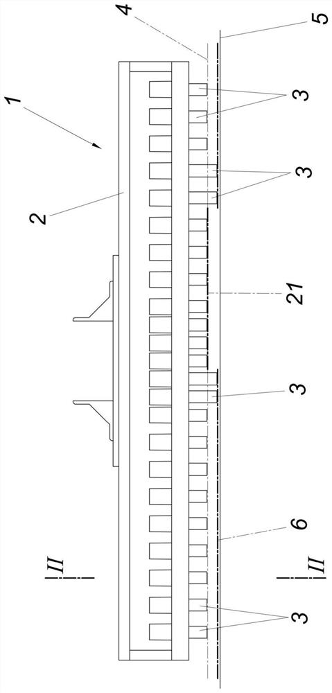
[0017] The gripper 1 according to the invention has a frame 2 in which a plurality of gripping elements 3 are arranged. These gripping elements 3 form a reference plane 4 which extends parallel to a flat support 5 for a material web 6, for example pre-impregnated or dry fiber material, a material or leather web, a film or analog. The gripping elements 3 are distributed in a grid-like manner in the reference plane 4, as can be obtained from Figure 5 seen in. The grid-like distribution does not have to be uniform. A denser distribution can be provided in areas where the outlines of individual billets are piled up, such as by Figure 5 The center area of ​​the gripper 1 is shown.

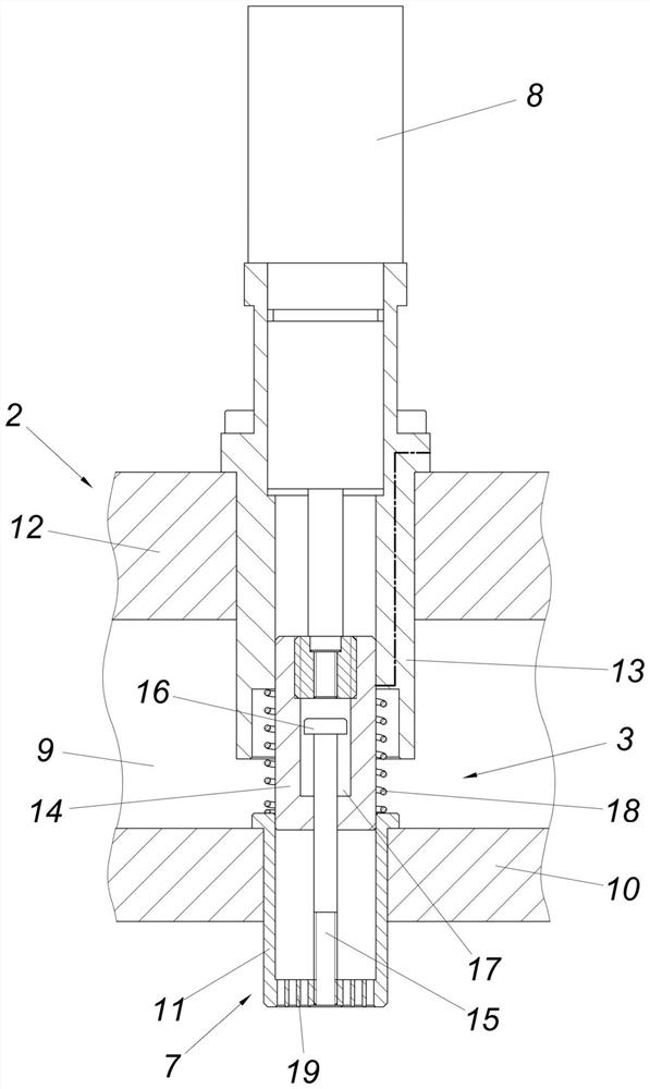
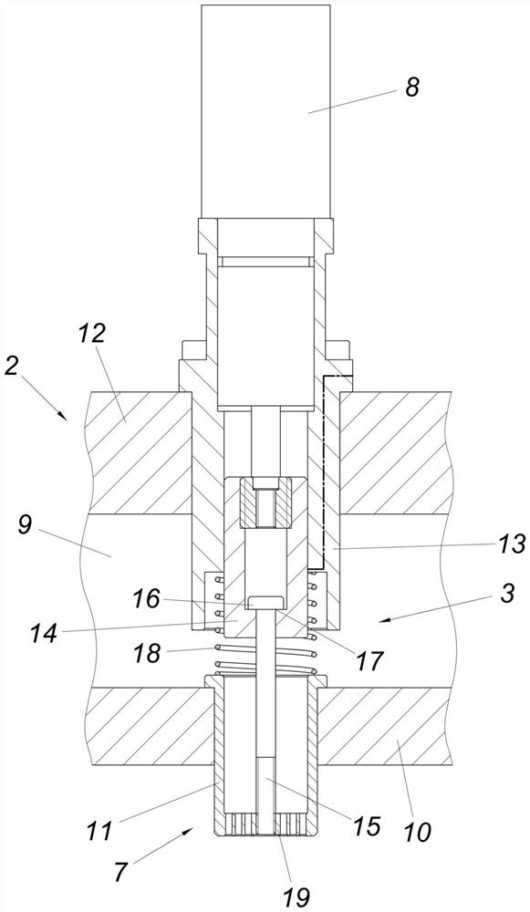
[0018] Although the gripping element 3 can, depending on the properties of the material web 6, clamp the blank, for example mechanically or magnetically, for most applications an advantageous dimension is obtained with the gripping element 3 forming the suction head 7, as shown in Figures 2 to 4...


PUM


Abstract

The invention relates to a method for controlling a gripper (1), which removes blanks (21) from a flat-lying material web (6) and comprises individually actuatable gripper elements (3), which define a reference plane (4) parallel to the material web (6) and are distributed in a grid-like manner in said reference plane (4), and which are adjustably mounted independently of each other in a frame (2) and perpendicular to the reference plane (4), wherein the gripper elements (3) are positioned and actuated onto the material web (6) in a receiving position of the gripper (1), oriented opposite the blank (21), by means of a control device according to the specified size and contour (22) of the blank (21). In order to create advantageous removal conditions, according to the invention, in addition to the gripper elements (3) located in the oriented receiving position of the gripper (1) within the contour (22) of the blank (21), at least gripper elements (3) adjacent to the blank (21) and located outside of the contour thereof (22) are positioned onto the material web (6) as hold-down means, and solely the gripper elements (3) within the contour (22) of the blank (21) are actuated and withdrawn so as to take the blank (21) along from the material web (6) before the gripper (1) is raised out of the receiving position from the material web (6).

Description

technical field [0001] The invention relates to a method for controlling grippers that remove a blank from a flatly supported web of material and that include, respectively operable in themselves, determining a reference plane parallel to the web and presenting in this reference plane grid-like distribution of gripping elements which are mounted independently of one another in a frame which can be adjusted perpendicularly to the reference plane, wherein the gripping elements are in the receiving position of the gripper aligned with respect to the blank by means of a control device The material web is placed against and manipulated according to a predetermined contour of the blank, and a gripper for carrying out the method is involved. Background technique [0002] In order to be able to remove blanks of different shapes and sizes from a fiber layer lying flat on the cutting table, it is known (DE 10 2008 032 574 A1) to use a gripper with a plurality of suction heads which ar...

Claims


Application Information

Patent Timeline
Patent Type & Authority Applications(China)
IPC IPC(8): B25J15/00B25J15/06B26D7/18B65G47/91B65H5/10B65H5/14B65H35/00
CPCB25J15/0052B25J15/0616B26D7/1863B65G47/918B65H5/14B65H35/00B65H5/10B65G47/917B65H2406/351B65H2406/342G05B2219/39558B65H2406/31B25J15/0625B65H29/241B65H2406/30G05B2219/39001
Inventor H.迪塔克迈尔
Owner GFM GMBH
Why Eureka
Try Eureka