Support for fitting out door unit of split air conditioner

A technology for air-conditioning devices and mounting brackets, which is applied in the direction of air-conditioning systems, heating methods, supporting machines, etc., which can solve the problems of loss of appearance and large impact, and achieve the effect of maintaining the effect

Inactive Publication Date: 2004-01-28
PANASONIC CORP
View PDF0 Cites 0 Cited by
  • Summary
  • Abstract
  • Description
  • Claims
  • Application Information

AI Technical Summary

Problems solved by technology

[0006] However, after the outdoor unit 41 is installed on the wall, when performing piping and wiring work between the indoor unit, depending on the installation place of the outdoor unit 41, sometimes the piping and wiring need to be pulled around the side of the outdoor unit 41. At this time, in ...

Method used


Image

  • Support for fitting out door unit of split air conditioner
  • Support for fitting out door unit of split air conditioner
  • Support for fitting out door unit of split air conditioner

Examples


Embodiment Construction

[0022] Embodiments of the present invention will be described below with reference to the drawings.

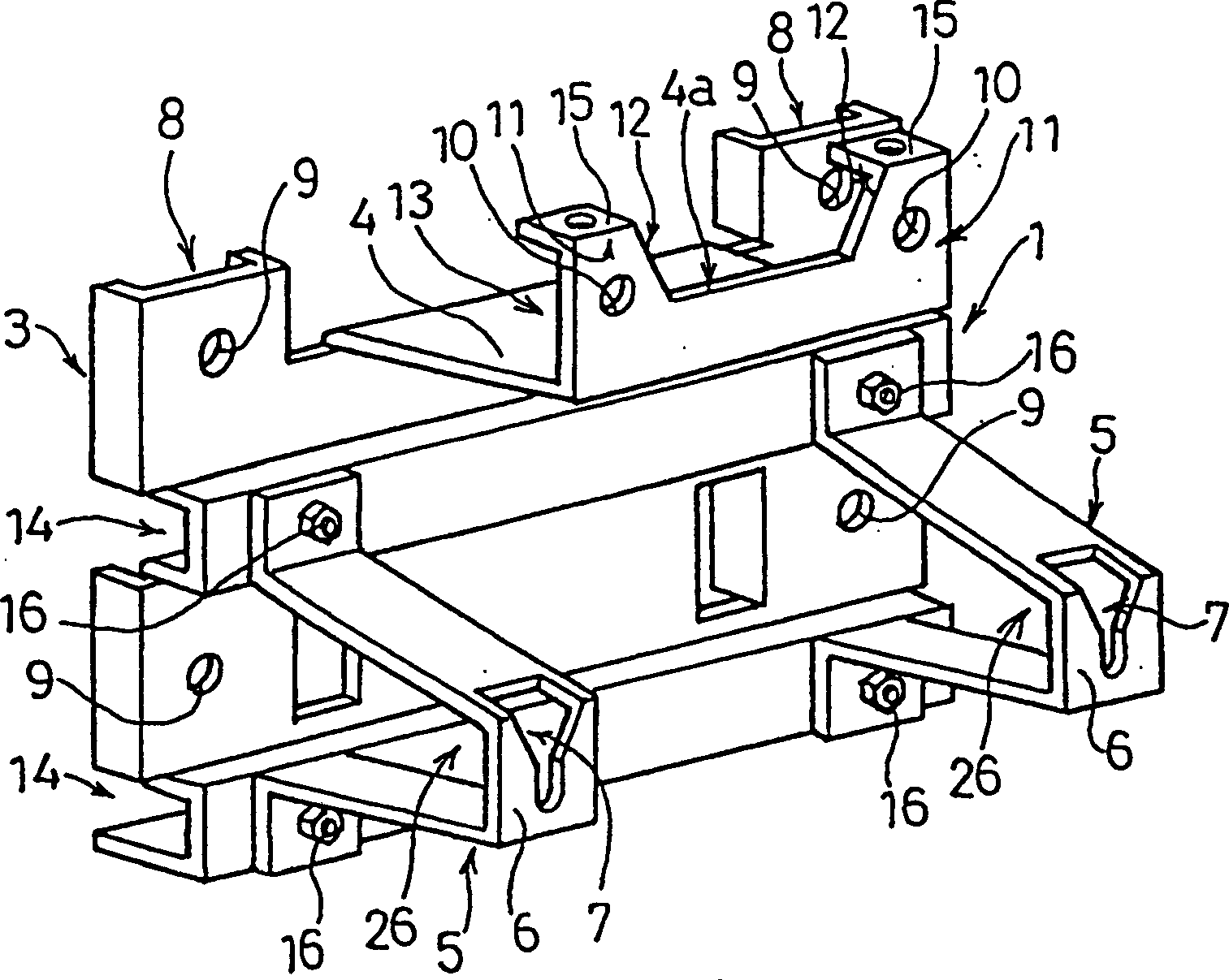
[0023] In one embodiment of the outdoor unit mounting bracket of the split-type air conditioner of the present invention, a surface mounting portion 3, a first support portion 4, and a pair of left and right second support portions 5 are provided. surface mount part 3 for figure 1 Sheet metal as shown, flush against wall and bolted face-to-face. The first support portion 4 is formed by protruding the upper portion of the surface mounting portion 3 forward, then bending upward, and extending left and right. The base of the second support part 5 is fixed to the front surface of the surface mounting part 3 below the first support part 4 with bolts 16 .

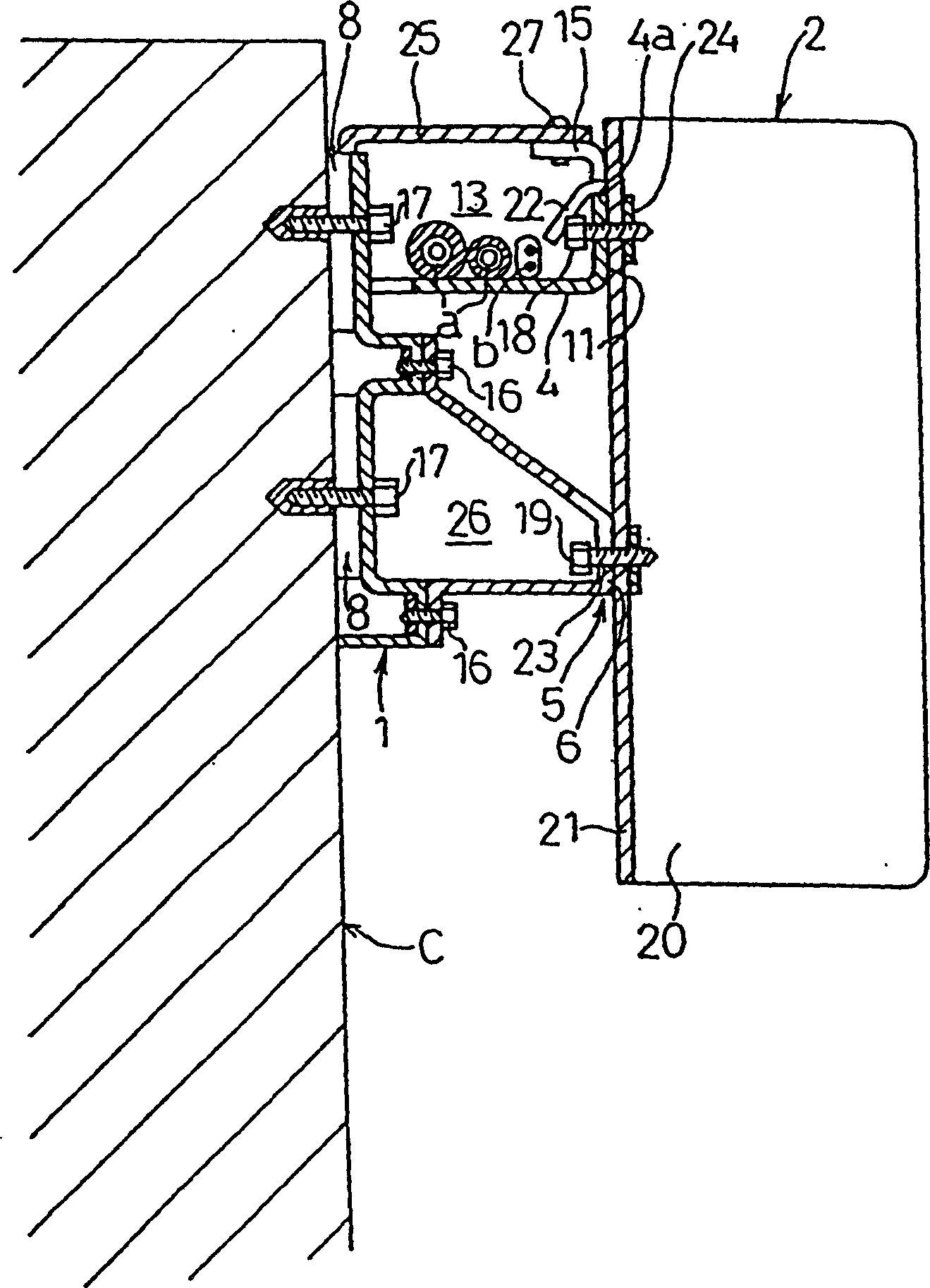
[0024] As an example of the outdoor unit 2, such as image 3 As shown, a first mounting part 22 and a second mounting part 23 are provided. The first installation part 22 is integrally provided on the upper part of the back ...


PUM


Abstract

A unit installation tool facilitates installation of a unit of a separate type air conditioner on a vertical member, preventing exposure of conduit to the elements, and improves the appearance. The tool has a yoke fitted to the vertical member with bolts, and a support part extended forward from the yoke, for mounting the upper part of the back side of the unit on its leading end. The mounted unit is supported at an upward position by a specified extent from the support part. A conduit space is formed on the support port between the supported outdoor unit and the yoke or the vertical member on which it is mounted.

Description

technical field [0001] The invention relates to an outdoor unit installation bracket of a split type air conditioner, which is used for installing the outdoor unit of the split type air conditioner on a wall. Background technique [0002] As shown in Figure 8, in order to reduce the structure of the unshown indoor unit and make it lighter and smaller, the outdoor unit 51 of the split type air conditioner accommodates more equipment, and the relatively heavy compressor 53 and the like are accommodated in the box body. within 52. Therefore, the outdoor unit 51 is heavier than the indoor unit, and usually utilizes the mounting feet 54 located at the bottom to be installed on a seat provided on the ground, balcony or roof. The mounting leg 54 has a mounting hole 54a for mounting to the mounting base, and is firmly fixed to the mounting base with bolts. However, sometimes the outdoor unit 51 is mounted on the wall because there is no space for installing the stand. [0003] As...

Claims


Application Information

Patent Timeline
IPC IPC(8): F16M13/02F24F1/62F24F5/00F24F13/32
CPCF24F13/32F24F1/62
Inventor 西俊治波多野弘司中沼三雄
Owner PANASONIC CORP
Why Eureka
Try Eureka