Laser radar system

A laser radar and light source unit technology, applied in the field of laser radar research, can solve the problems of difficult manufacturing, easy wear and tear of rotating parts, unfavorable mass production, etc., and achieves the effects of convenient installation and calibration, simple use and installation, and simple structure

Pending Publication Date: 2021-11-12
江西上科极星光电技术有限公司
View PDF0 Cites 2 Cited by
  • Summary
  • Abstract
  • Description
  • Claims
  • Application Information

AI Technical Summary

Problems solved by technology

At present, lidar mainly includes mechanical rotating lidar and splicing MEMS radar. Mechanical rotating lidar drives the transmitting module and receiving module to rotate 360° by the rotating part to obtain the surrounding environment distance signal. However, the above-mentioned mechanical rotating lidar has many shortcomings. : Multi-line (such as 32-line, 64-line) laser radar transmitting module and receiving module are set in pairs, which requires high angle setting and is difficult to manufacture, which is not conducive to mass production and high price; its rotating parts are easy to wear and even failure, requires regular maintenance
Splicing MEMS radars have advantages over mechanical radars in terms of service life and maintenance. However, the horizontal field of view of MEMS lidars is usually only about 45°. If a larger field of view is required, it can only be achieved by splicing. Generally, 3-5 optical path splicing is required to achieve large-angle target scanning. The same device needs to use multiple paths, which is expensive

Method used


Image

  • Laser radar system
  • Laser radar system
  • Laser radar system

Examples


Embodiment Construction

[0025] The present invention will be further described in detail below in conjunction with the accompanying drawings and specific embodiments. According to the following description, the purpose, technical solution and advantages of the present invention will be more clear. It should be noted that the described embodiments are preferred embodiments of the present invention, but not all embodiments.

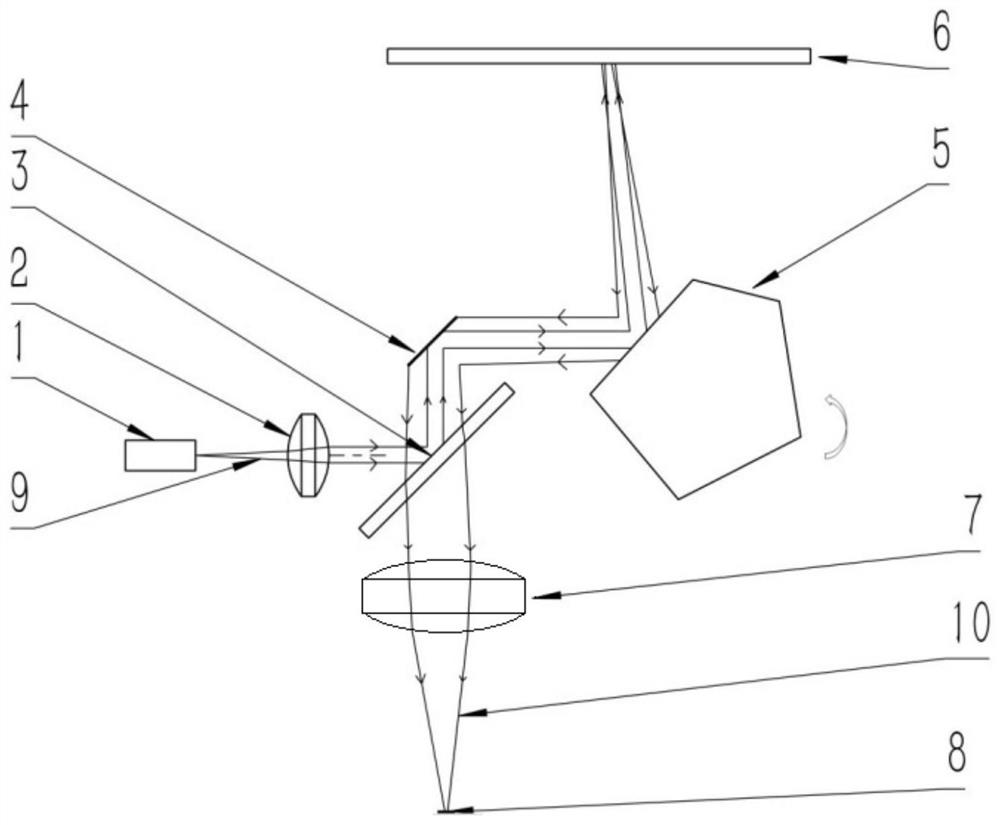
[0026] combine figure 1 As shown, a laser radar system includes a light source unit, a scanning unit and a receiving unit.

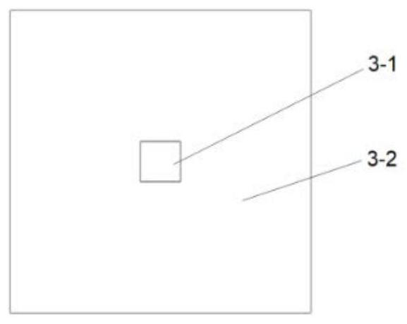
[0027] The light source unit includes a laser 1, a collimating mirror 2 and a special lens 3, refer to figure 2 , the central area of ​​the special lens 3 is coated with a reflective film 3-1, which can totally reflect the light beam, and the special lens 3 is coated with an anti-reflection film 3-2 in the area other than the central area, through which the laser light can pass. The central area of ​​special lens 3 is relatively small, and the area coate...


PUM


Abstract

The invention relates to a laser radar system which comprises a light source unit, a scanning unit and a receiving unit, the light source unit comprises a laser, a collimating lens and a special lens, the central area of the special lens is plated with a reflecting film, the area, except the central area, of the special lens is plated with an antireflection film, the scanning unit comprises a mems galvanometer and a prism controlled by a motor, the mems galvanometer has scanning angles in the vertical direction and the horizontal direction and can control laser incident on a reflecting surface to be emitted in the two directions, and the receiving unit comprises a special lens, a focus lens and a sensor. According to the invention, beam expanding scanning can be carried out through the mems galvanometer and the prism controlled by the motor to rotate, accurate detection scanning of the environment is realized, beam expanding can be realized without a splicing mode, and the cost is greatly saved.

Description

technical field [0001] The invention relates to a laser radar system, belonging to the technical field of laser radar research. Background technique [0002] LiDAR is a laser detection and ranging system LiDAR (Light Detection and Ranging), which is a radar system that detects the position, speed and other characteristic quantities of a target by emitting a laser beam. Its working principle is to first send a detection laser beam to the target, then the receiver receives the signal reflected from the target, and finally the laser radar compares the reflected signal with the transmitted signal, and after proper processing, the relevant information of the target can be obtained, such as the target Parameters such as distance, orientation, height, speed, attitude, and even shape. Due to the inherent advantages of lidar in environmental perception, it has a good application prospect in areas such as unmanned driving and obstacle avoidance. At present, lidar mainly includes mec...

Claims


Application Information

Patent Timeline
Patent Type & Authority Applications(China)
IPC IPC(8): G01S7/481
CPCG01S7/4817
Inventor 朱天凤王丽罗海燕徐彬袁山山钟义晖
Owner 江西上科极星光电技术有限公司
Why Eureka
Try Eureka