


Quick Research
Generate reliable direction feasibility study reports for your R&D in just a few steps.

Technical Q&A
Discover and master advanced knowledge NOW. Basics, ideas, possibilities, all at once.

Find Solutions
As an expert in R&D theories, this can generate solutions to your technical problems instantly.

Evaluate Feasibility
Analyze your overall solution with one click, know your potential R&D risks in advance.

Monitor Landscape
Get weekly tech updates, stay abreast of the latest tech innovations and key insights.
Air conditioner
A technology for air conditioners and air, which is used in air conditioning systems, space heating and ventilation, space heating and ventilation details, etc., and can solve problems such as condensation at the suction port
- Summary
- Abstract
- Description
- Claims
- Application Information
AI Technical Summary
Problems solved by technology
Method used
Image

Examples
Embodiment approach 1
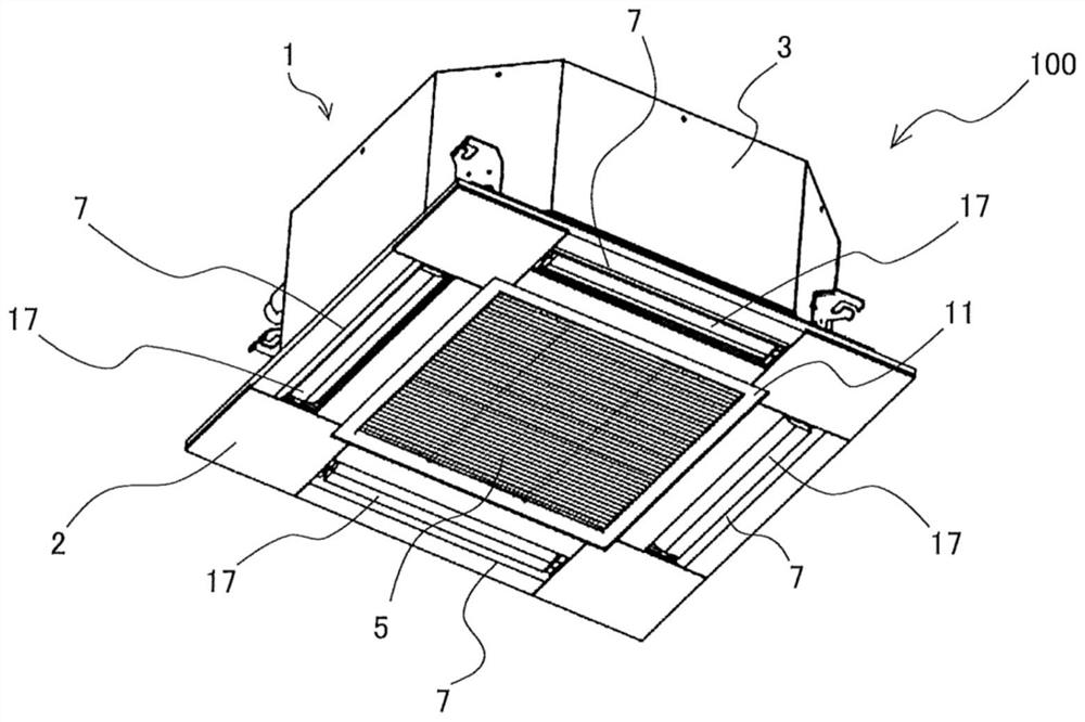
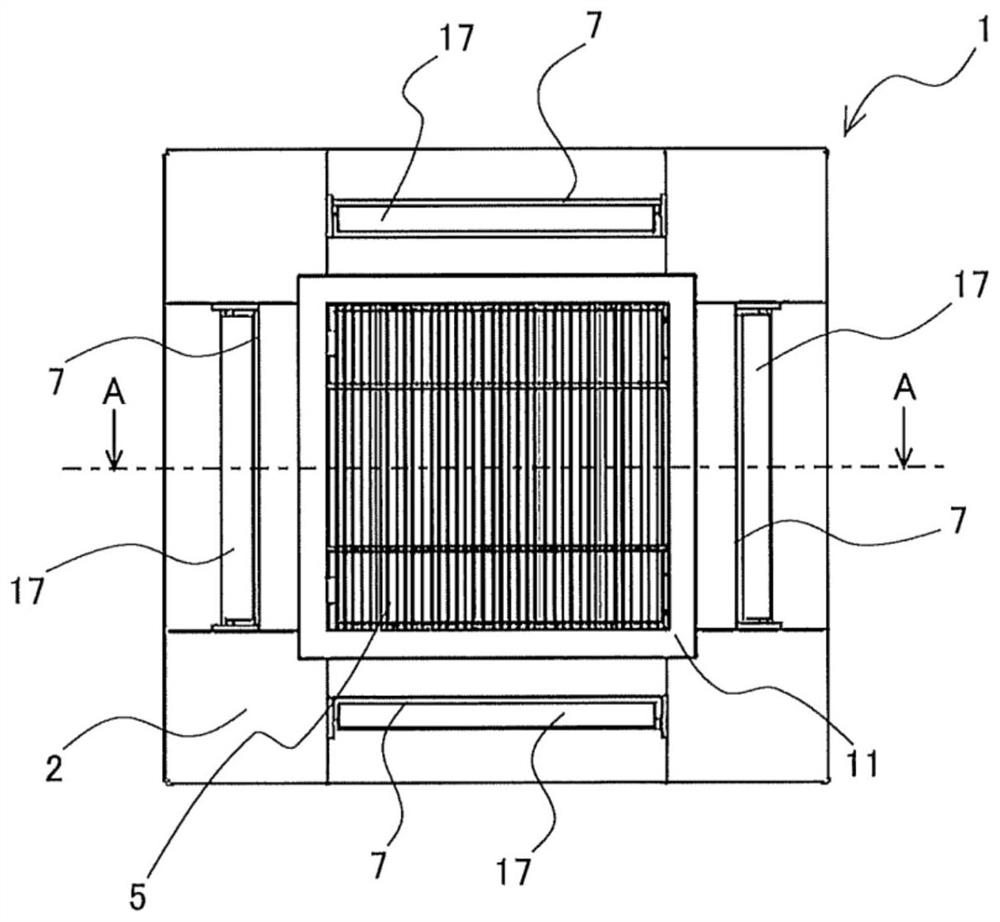
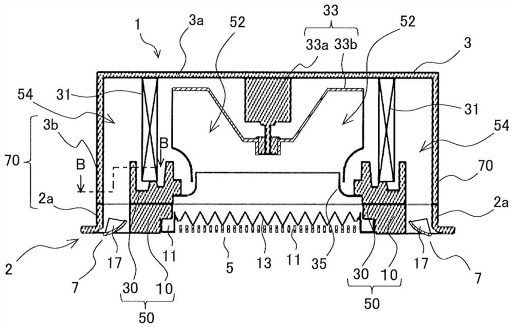
[0019] Air conditioner 100 according to Embodiment 1 will be described. figure 1 It is a perspective view schematically showing an example of the appearance structure of the indoor unit 1 of the air conditioner 100 according to the first embodiment. figure 2 Viewed from the surface side of the outer panel 2 figure 1 A schematic top view of the indoor unit 1. image 3 is roughly figure 2 Cutaway view of the A-A section. which, in the included Figure 1 ~ Figure 3 In the drawings included below, the dimensional relationship and shape of each component may be different from the actual ones. Additionally, when including Figure 1 ~ Figure 3 In the drawings below, the same components or parts or components or parts having the same function are given the same reference numerals or are omitted from the reference numerals. In addition, the positional relationship among the components of the indoor unit 1 , such as the positional relationship between up and down, left and right...
Embodiment approach 2
[0053] use Figure 8 and Figure 9 Embodiment 2 will be described. Figure 8 is a schematic representation of Embodiment 2 Figure 4 Cutaway view of the C-C section. Figure 9 is roughly Figure 8 Cutaway view of the E-E section. Also due to Figure 1~3 The structure of the shown indoor unit 1 is also the same in Embodiment 2, and therefore description thereof will be omitted. In the following description, only the configurations different from those of Embodiment 1 described above will be described.
[0054] Such as Figure 8 and Figure 9 As shown, in Embodiment 2, the air flow guide member 58 is provided on the upstream side of the wind velocity reducing member 56 . The air flow guiding member 58 is connected to the second air duct wall 70 . The airflow guide member 58 can be integrally formed with the second air duct wall 70 . Forming the airflow guide member 58 integrally with the second air duct wall 70 eliminates the need to attach the airflow guide member 58...
PUM
 Abstract
Description
Claims
Application Information
 - R&D Engineer
- R&D Manager
- IP Professional
- Industry Leading Data Capabilities
- Powerful AI technology
- Patent DNA Extraction
Browse by: Latest US Patents, China's latest patents, Technical Efficacy Thesaurus, Application Domain, Technology Topic, Popular Technical Reports.
© 2024 PatSnap. All rights reserved.Legal|Privacy policy|Modern Slavery Act Transparency Statement|Sitemap|About US| Contact US: help@patsnap.com