Charging topology network and direct current contactor control system and method in charging system

A DC contactor, topology network technology, applied in the direction of collectors, battery circuit devices, instruments, etc., can solve the problem of unstable charging, and achieve the effect of improving operation stability and operation efficiency

Pending Publication Date: 2021-11-05
绿能慧充数字技术有限公司
View PDF0 Cites 2 Cited by
  • Summary
  • Abstract
  • Description
  • Claims
  • Application Information

AI Technical Summary

Problems solved by technology

[0004] The purpose of the present invention is to provide a charging topology network and a DC contactor control system and method in the charging system to solve the technical problem of charging instability during the terminal power distribution process, and to ensure that the system can be accurately allocated according to the module under the premise of absolute safety. Changes in attributes dynamically adjust the switching of charging relays to achieve stable charging of all terminals in the system, thereby ensuring that the system outputs in an optimal state

Method used


Image

  • Charging topology network and direct current contactor control system and method in charging system
  • Charging topology network and direct current contactor control system and method in charging system
  • Charging topology network and direct current contactor control system and method in charging system

Examples


Embodiment 1

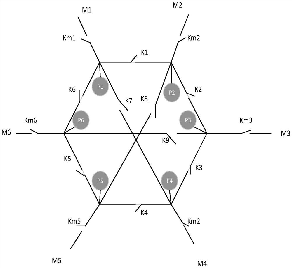
[0045] like figure 1 As shown, the charging topology network in the present invention includes: multiple sets of power modules, multiple sets of DC contactors and multiple sets of terminals;

[0046] Multiple sets of DC contactors include: multiple sets of first DC contactors K1, K2, K3, K4, K5, K6; multiple sets of second DC contactors K7, K8, K9 and multiple sets of main DC contactors Km1, Km2, Km3, Km4, Km5, Km6;

[0047] Multiple groups of power modules include power modules P1, P2, P3, P4, P5, and P6; first DC contactors K1, K2, K3, K4, K5, and K6 are connected in series to form a ring structure; power modules P1, P2, P3, and P4 , P5 and P6 are respectively connected to corresponding terminals M1, M2, M3, M4, M5 and M6 through a group of main DC contactors Km1, Km2, Km3, Km4, Km5 and Km6;

[0048] Each group of power modules is electrically connected to the main DC contactor connected to any group of non-adjacent power modules on the ring structure through a group of se...

Embodiment 2

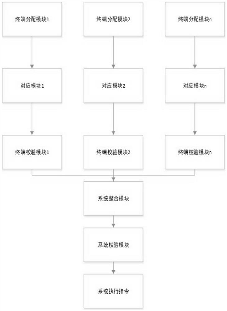
[0055] see figure 2 As shown, a DC contactor control system in a charging system includes: the charging topology network and a controller described in Embodiment 1; the controller includes:

[0056] Terminal allocation module: according to the power required by each terminal, allocate appropriate power modules;

[0057] Corresponding module: according to the allocated power module, obtain the closing status of the DC contactors K1-K9 under the corresponding power module;

[0058] Terminal verification module: verify the data obtained by the corresponding module according to the verification principle of each terminal, and obtain the closing status of the contactor of the terminal;

[0059] System integration module: Integrate the closing conditions of the contactors of all terminals to obtain the closing conditions of the DC contactors K1-K9 under each terminal;

[0060] System verification module: According to the system verification principle, the data obtained by the sys...

Embodiment 3

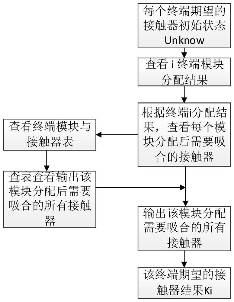
[0062] see image 3 As shown, the present invention provides a control method for a DC contactor control system in a charging system, comprising the following steps:

[0063] Obtain the power module allocation results of each terminal;

[0064] According to the allocated power modules, the closing expectation of the DC contactor corresponding to each power module is obtained;

[0065] According to the principle of terminal verification, judge the closure of each power module of the terminal and the DC contactor, and obtain the expected result of the terminal;

[0066] Integrate the expected results of each terminal to obtain the expected results of the system;

[0067] According to the principle of system verification, the expected result of the system is judged, and the final execution result of the system is obtained.

[0068] In the present invention, the terminal verification principle means that the same contactor that has a pull-in expectation under the terminal can o...


PUM


Abstract

The invention belongs to the technical field of power electronics, and discloses a charging topology network and a direct current contactor control system and method in a charging system. The charging topology network comprises a plurality of groups of power modules, a plurality of groups of direct current contactors and a plurality of groups of terminals. The plurality of groups of direct current contactors comprise a plurality of groups of first direct current contactors, a plurality of groups of second direct current contactors and a plurality of groups of main direct current contactors; the plurality of groups of power modules are composed of at least two groups of power modules; each group of power modules is connected with at least one group of first direct current contactors, and the multiple groups of first direct current contactors are connected in series to form an annular structure; each group of power modules is connected with a corresponding terminal through a group of main direct current contactors; and each group of power modules is electrically connected with the direct current contactors connected with any one group of non-adjacent power modules on the annular structure through one group of second direct current contactors. According to the invention, different contactors are attracted to form different channels which are connected with different power modules to form a power pool of the terminal, so that the purpose of power switching is achieved.

Description

technical field [0001] The invention belongs to the technical field of power electronics, and in particular relates to a DC contactor control system and method in a charging topology network and a charging system. Background technique [0002] With the rapid development of various electrical equipment, there are more and more charging equipment. For example, using electric vehicles as the development plan for new energy vehicles has become a major project for energy conservation, emission reduction, and promotion of industrial upgrading. Charging equipment provides energy supply for electrical equipment and has become an important support system for electrical equipment. [0003] In recent years, the high-power flexible intelligent charging system has gradually developed, and there are more and more matrix circuits built by DC contactors. The output power of the existing charging system is fixed when it is used, and it cannot output appropriate power according to different ...

Claims


Application Information

Patent Timeline
IPC IPC(8): G06F30/20H02J7/00G06F119/02
CPCG06F30/20H02J7/00G06F2119/02
Inventor 白云海吕军锋张勃雒建华黄晓英
Owner 绿能慧充数字技术有限公司
Why Eureka
Try Eureka