
High-position automatic water spraying noise reduction system following rocket exhaust plume

A technology of noise reduction system and water supply system, which is applied in the direction of rocket launcher, offensive equipment, weapon type, etc. It can solve the problems that the noise reduction water cannot reach in time and affect the noise reduction effect of high-level water spraying, so as to avoid low-frequency vibration, Reduced water hammer effect and excellent noise reduction performance

Active Publication Date: 2021-11-05
NO 63921 UNIT OF PLA +1
View PDF6 Cites 0 Cited by
  • Summary
  • Abstract
  • Description
  • Claims
  • Application Information

AI Technical Summary

Problems solved by technology

At present, the high-level water spray lags behind the rocket’s take-off time. In the initial stage of the rocket’s take-off, the water spray and noise reduction system failed to start due to concerns that the mis-spray would affect the rocket body. The noise reduction water could not reach the engine jet area in time, and the water spray and noise reduction system was activated At this time, the rocket body has been flying far away from the ground, which affects the noise reduction effect of the high-level water spray

Method used


Image

  • High-position automatic water spraying noise reduction system following rocket exhaust plume
  • High-position automatic water spraying noise reduction system following rocket exhaust plume
  • High-position automatic water spraying noise reduction system following rocket exhaust plume

Examples


Embodiment Construction

[0028] The present invention will be described in detail below with reference to the accompanying drawings and examples.

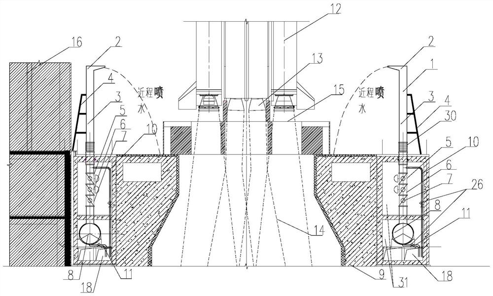
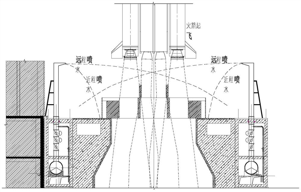
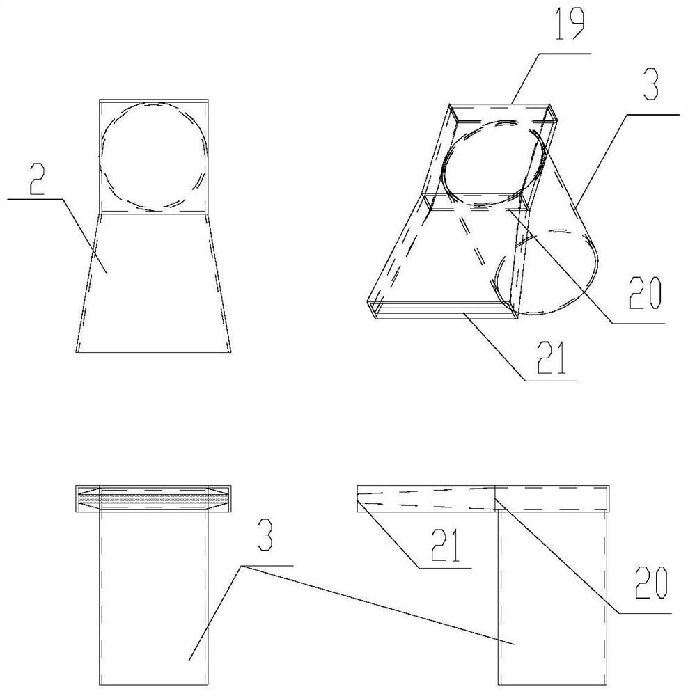
[0029] as attached figure 1 with 2 As shown, the present invention provides a high-level automatic water spray noise reduction system following rocket plume, which system includes nozzle 2, water spray pipeline 3, fast valve control system, air supply system, water supply system and drainage system.

[0030] Wherein, the water supply system is located at the top of the launch tower 16, and the nozzles 2 are connected to the water supply system through the water spray pipeline 3. The nozzles 2 are evenly arranged on the front and rear sides of the launch station. After the nozzles 2 spray water stably, the water spray range can cover the launch platform 15. , just below the launch pad 15 is a diversion groove 9 for guiding gas jets and cooling and noise-reducing water vapor. Image 6 shown.

[0031] The rapid valve control system is set on the water spra...


PUM


Abstract

The invention discloses a high-position automatic water spraying noise reduction system following rocket exhaust flame, and belongs to the technical field of rocket launching noise protection. The system comprises nozzles, a quick valve control system, an air supply system, a water supply system and a drainage system; the nozzles are connected to the water supply system through water spraying pipelines, and evenly arranged on the front side and the rear side of a launching station; and the water spraying range can cover a launching pad after stable water spraying of the nozzles. The rapid valve control system is arranged on a water supply pipeline, and short-range water spraying of the system is achieved before ignition of a rocket engine; long-range water spraying of the system is achieved at a certain moment after a rocket is ignited to take off, and the time interval between the working conditions of short-range water spraying and long-range water spraying is about 1 s; the air supply system is used for providing compressed air for the quick valve control system as a control air source; and large-flow sprayed water is timely collected and discharged to a low-lying position outside a launching site through the drainage system. According to the system, the working conditions of water spraying are switched according to the rocket launching conditions, the safety of a rocket body can be guaranteed, and meanwhile noise radiation and propagation are restrained.

Description

technical field [0001] The invention relates to a high-position automatic water spray noise reduction system following a rocket tail flame, belonging to the technical field of rocket launch noise protection. Background technique [0002] When the medium and large bundled carrier rockets are launched, the jets of the first stage and the booster engine will produce aerodynamic noise of more than 170dB, which will cause acoustic vibrations on the rocket and the weak structural parts of the launch system, and sound-sensitive electrical components, causing destructive effects and affecting the launch. The environment around the field and the test personnel will also cause harm. When the rocket is ignited, water is sprayed into the engine gas jet field to change the noise generation mechanism and suppress the noise propagation, which can effectively reduce the noise value around the rocket. At present, the high-level water spray lags behind the rocket’s take-off time. In the init...

Claims


Application Information

Patent Timeline
IPC IPC(8): F41F3/04
CPCF41F3/04
Inventor 刘俊林张志成李玉良宋道宏陈丹亢勇唐小松崔展鹏季会媛陈默周云龙
Owner NO 63921 UNIT OF PLA
Learn More